Showing posts with label 70. Show all posts
Showing posts with label 70. Show all posts
Wednesday, November 20, 2013
140W Amplifier Circuit 2x 70 Watt
Stereo Power Amplifier is 2x70Watt STA550 chip audio power with BASH concept that can be connected with digital perangkkat. 2x70Watt STA550 Stereo Power Amplifier is an amplifier with BTL system with symmetrical power supply with ground. Power amplifier STA550 uses power output transistor which is on the chip and is set to produce a high efficiency audio power.
Power output on the STA550 is using the system without copling ac bridge (direct) and zero offset. Strengthening of the STA550 from stereo power amplifier is +12 dB. 2x70Watt STA550 Stereo Power Amplifier is equipped with temperature sensors for protection from overheating and current-limiting protection system for power amplifier. 2x70Watt STA550 Stereo Power Amplifier is equipped with standby and mute controls to regulate silent or active mode power amplifier.
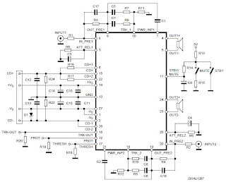
Feature Stereo Power Amplifier 2x70Watt STA550 :
Monochip Bridge Stereo Amplifier dengan Bash® Architecture55+55w Output Power @ Rl = 4/8 W, Thd = 0.5%
70+70w Output Power @ Rl = 4/8 W, Thd = 10%
High Dynamic Preamplifier Input Stages
External Programmable Feedback Type Compressors
Ac Coupled Input To Class Ab Bridge Output Amplifier
Precision Rectifiers To Drive The Digital Converter
Proportional Over Power Output Current To Limit The Digital Converter
Absolute Power Bridge Output Transistor Power Protection
Absolute Output Current Limit
Integrated Thermal Protection
Power Supply Over Voltage Protection Flexiwatt Power Package With 27 Pin
Bash® Licence Required

Friday, November 8, 2013
70 260VAC to180 350VDC voltage converter
Using circuit diagram below can be built a voltage converter, able to convert a 70-260V AC to a 180-350V DC voltage.
For this, a rectifier contained in a MC34161 is used, as a voltage doubler for low input voltages and as rectifier for high standard input voltage.
A variation of four times of the input voltage is reflected in a variation of not more than two times in output voltage.
MC34161 has included a reference voltage source which supplies a voltage of 2.54 V to pin 1. The signal applied to pin 2 is compared with internal voltage of 1.27 V.
R2-R3 voltage divider provides change state of internal comparator which grow output input voltage over 135 V (pin 5 passes in 1 state). The potential at pin 2 is less than 1.27 V. Triac is blocked and disconnects median connection between the two output capacitors, C2 and C3, such that doubling output voltage can not be produced
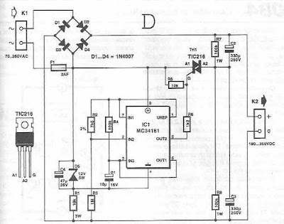
- When the input voltage is less than 135 V, pin 2 is maintained above the potential value of 1.27 V
- Diodes D2 and D3 and capacitors C2 and C3 will function as voltage doubler.
- Zener diode D5, together with R1 and C4, integrated circuit provides power to a stable source of 12 V. The time required passing standard rectifier circuit of the voltage doubler is determined by R4-C1.
- Operating voltage of capacitors C2 and C3 must be> 250 V.
Subscribe to:
Posts (Atom)