Showing posts with label converter. Show all posts
Showing posts with label converter. Show all posts
Wednesday, December 25, 2013
Anti Log Converter Schematic Circuits
 Anti-Log Converter Schematic Circuits
Anti-log or exponential bearing is artlessly a amount of rearranging the logarithmic circuitry. The ambit diagram beneath shows the chip of the log adapted to accomplish an exponential achievement from a beeline input.
The emitter of Q2 in admeasurement to the ascribe voltage is apprenticed by amplifier A1 in affiliation with transistor Q1. The beneficiary accepted of Q2 varies exponentially with the emitter-base voltage.
Thursday, November 21, 2013
Frequency to Voltage Converter
Overview of IC LM2917 as Frequency to Voltage Converter
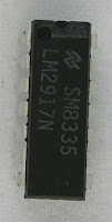 Very easy to apply in measuring the output frequency with the formulation of single-chip Frequency to Voltage Converter VOUT = FIN x VCC x R1 x C1. Then the single-chip LM2917 Frequency to Voltage Converter This configuration requires only the RC only in frequncy doublings. And has an internal zener regulator to aimlessly accuracy and stability in frequency-to-voltage conversion process.
Next full text...
IC LM2917 IC chip is designed specifically as a Frequency to Voltage Converter or Frequency to Voltage converter. In its use to applications Frequency to Voltage Converter IC LM2917 requires few external components.
There are several examples of applications of Frequency to Voltage Converter IC LM2917 is supplied in the LM2917 IC datahseet. In this article series Frequency to Voltage Converter IC also taken from the LM2917 datasheet. The advantages of single chip LM2917 Frequency to Voltage Converter is able to provide instantaneous volt output o at time of frequency change 0 Hz.
There are several examples of applications of Frequency to Voltage Converter IC LM2917 is supplied in the LM2917 IC datahseet. In this article series Frequency to Voltage Converter IC also taken from the LM2917 datasheet. The advantages of single chip LM2917 Frequency to Voltage Converter is able to provide instantaneous volt output o at time of frequency change 0 Hz.
Very easy to apply in measuring the output frequency with the formulation of single-chip Frequency to Voltage Converter VOUT = FIN x VCC x R1 x C1. Then the single-chip LM2917 Frequency to Voltage Converter This configuration requires only the RC only in frequncy doublings. And has an internal zener regulator to aimlessly accuracy and stability in frequency-to-voltage conversion process. |
| Frequency to Voltage Converter |
Feature-owned single-chip LM2917 Frequency to Voltage Converter
- Reference to ground directly with variable reluctance
- Op Amp / Comparator with transistor output
- 50 mA maximum output currents for application directly to the load
- Frequency doubling untul low ripel
- Buid in zener
- Linear output ± 0.3%
Application single chip LM2917 Frequency to Voltage Converter
- Frequency to Voltage Converter
- Rotation speed sensor applications
- Speedometer
- Tachometer
- Cruise Control
- Cluth Control
And other application associated with the measurement of rotation speed or frequency measurements.
Monday, November 18, 2013
DC DC Converter 12V to 24V
This simple circuit is a DC-DC converter that converting up 12V source to a 24V. It can be used to run radios, small lights, relays, horns and other 24V accessories from a 12V vehicle with a maximum draw of about 800mA.
This DC-DC Converter can be used to charge one 12V battery from another, or step up the voltage just enough to provide necessary overhead for a 12V linear regulator. Using one op-amp as a squarewave oscillator to ring an inductor and another op-amp in a feedback loop, it wont drift around under varying loads, providing a stable 24V source for many applications. With a wide adjustment in output this circuit has many uses.
Parts List
R1-R4,R7-R8 100K 1/4W Resistor
R5 470 Ohm 1/2W Resistor
R6 10K Linear Pot
C1 0.01uF Mylar Capacitor
C2 0.1uF Ceramic Disc Capacitor
C3 470uF 63V Electrolytic Capacitor
D1 1N4004 Rectifier Diode
D2 BY229-400 Fast Recovery Diode See Notes
Q1 BC337 NPN Power Transistor
U1 LM358 Dual Op Amp IC
L1 See Notes
MISC Board, Wire, Socket For U1, Case, Knob For R6, Heatsink for Q1
DC- DC Converter Notes
1. R6 sets the output voltage. This can be calculated by Vout = 12 x (R8/(R8+R7)) x (R6B/R6A).
2. L1 is made by winding 60 turns of 0.63MM magnet wire on a toroidial core measuring 15MM (OD) by 8MM (ID) by 6MM (H).
3. D2 can be any fast recovery diode rated at greater then 100V at 5A. It is very important that the diode be fast recovery and not a standard rectifier. 4. Q1 will need a heatsink.
12V to 30V DC to DC Converter Schematic
12V to +/- 30V DC to DC Converter Circuit Diagram

This is a DC to DC converter for car power amplifier. 12V input generates +30V and -30V output for preamp or power amplifiers. Circuit uses SG3525 IC, Mosfets and switching power supply.
Sunday, November 17, 2013
Converter with 2N3055 transistors
This plain converter using a Zener diode and a transistor into a 9V DC 12V DC battery power to the most 1A. The circuit is very simple to build, and requires just 3 electronic components, resistors, zener diodes and transistors. The 2N3055 transistors, 1N4738A Zener diode before Zener voltage and the same power. 3W, and perhaps wire wound resistor 3R type. Powering a expedient tool to avail yourself of 9V DC.
 |
| Converter with 2N3055 transistors |
The output voltage of the following formula:
Zener voltage Vout = + 0.65V, 0.65V, which is the heart-emitter voltage of transistors
Friday, November 8, 2013
70 260VAC to180 350VDC voltage converter
Using circuit diagram below can be built a voltage converter, able to convert a 70-260V AC to a 180-350V DC voltage.
For this, a rectifier contained in a MC34161 is used, as a voltage doubler for low input voltages and as rectifier for high standard input voltage.
A variation of four times of the input voltage is reflected in a variation of not more than two times in output voltage.
MC34161 has included a reference voltage source which supplies a voltage of 2.54 V to pin 1. The signal applied to pin 2 is compared with internal voltage of 1.27 V.
R2-R3 voltage divider provides change state of internal comparator which grow output input voltage over 135 V (pin 5 passes in 1 state). The potential at pin 2 is less than 1.27 V. Triac is blocked and disconnects median connection between the two output capacitors, C2 and C3, such that doubling output voltage can not be produced
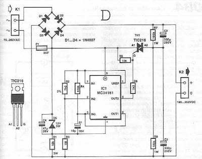
- When the input voltage is less than 135 V, pin 2 is maintained above the potential value of 1.27 V
- Diodes D2 and D3 and capacitors C2 and C3 will function as voltage doubler.
- Zener diode D5, together with R1 and C4, integrated circuit provides power to a stable source of 12 V. The time required passing standard rectifier circuit of the voltage doubler is determined by R4-C1.
- Operating voltage of capacitors C2 and C3 must be> 250 V.
Friday, November 1, 2013
555 Timer for DC to DC Converter Circuit
 |
| 555 Timer for DC to DC Converter |
This circuit is called DC TO DC converter circuit.Which increase the voltage circuit.There can be customized to change the output values. When the power supply input to IC1 is the output pin 3 at a frequency of 1 kHz.The frequency is Q1 and Q2, which will continue to use push pool work interchangeably.If this is the positive output signal Q1 Q2 will run the delete function this reason, C2 and C3 capacitors are half-wave alternating.When to use. Voltage from C2 to C3 is discharged out to the input voltage over almost two times less than 2 times due to the loss of diodes D1-D3.
Sunday, October 6, 2013
6 to 12 Volt Converter
Below its a converter circuit voltage from 6 Volt to 12 Volt DC.
 |
| 6 Volt to 12 Volt DC |
Part List :
R1, R4 2 .2K 1/4W Resistor
R2, R3 4.7K 1/4W Resistor
R5 1K 1/4W Resistor
R6 1.5K 1/4W Resistor
R7 33K 1/4W Resistor
R8 10K 1/4W Resistor
C1,C2 0.1uF Ceramic Disc Capacitor
C3 470uF 25V Electrolytic Capcitor
D1 1N914 Diode
D2 1N4004 Diode
D3 12V 400mW Zener Diode
Q1, Q2, Q4 BC547 NPN Transistor
Q3 BD679 NPN Transistor
L1 See Notes
Notes
1. L1 is a custom inductor wound with about 80 turns of 0.5mm magnet wire around a toroidal core with a 40mm outside diameter.
2. Different values of D3 can be used to get different output voltages from about 0.6V to around 30V. Note that at higher voltages the circuit might not perform as well and may not produce as much current. You may also need to use a larger C3 for higher voltages and/or higher currents.
3. You can use a larger value for C3 to provide better filtering.
4. The circuit will require about 2A from the 6V supply to provide the full 800mA at 12V.
Monday, September 23, 2013
Frequency to Voltage Converter
Overview of IC LM2917 as Frequency to Voltage Converter
Very easy to apply in measuring the output frequency with the formulation of single-chip Frequency to Voltage Converter VOUT = FIN x VCC x R1 x C1. Then the single-chip LM2917 Frequency to Voltage Converter This configuration requires only the RC only in frequncy doublings. And has an internal zener regulator to aimlessly accuracy and stability in frequency-to-voltage conversion process.
Next full text...
IC LM2917 IC chip is designed specifically as a Frequency to Voltage Converter or Frequency to Voltage converter. In its use to applications Frequency to Voltage Converter IC LM2917 requires few external components.
There are several examples of applications of Frequency to Voltage Converter IC LM2917 is supplied in the LM2917 IC datahseet. In this article series Frequency to Voltage Converter IC also taken from the LM2917 datasheet. The advantages of single chip LM2917 Frequency to Voltage Converter is able to provide instantaneous volt output o at time of frequency change 0 Hz.
There are several examples of applications of Frequency to Voltage Converter IC LM2917 is supplied in the LM2917 IC datahseet. In this article series Frequency to Voltage Converter IC also taken from the LM2917 datasheet. The advantages of single chip LM2917 Frequency to Voltage Converter is able to provide instantaneous volt output o at time of frequency change 0 Hz.
Very easy to apply in measuring the output frequency with the formulation of single-chip Frequency to Voltage Converter VOUT = FIN x VCC x R1 x C1. Then the single-chip LM2917 Frequency to Voltage Converter This configuration requires only the RC only in frequncy doublings. And has an internal zener regulator to aimlessly accuracy and stability in frequency-to-voltage conversion process. |
| Frequency to Voltage Converter |
Feature-owned single-chip LM2917 Frequency to Voltage Converter
- Reference to ground directly with variable reluctance
- Op Amp / Comparator with transistor output
- 50 mA maximum output currents for application directly to the load
- Frequency doubling untul low ripel
- Buid in zener
- Linear output ± 0.3%
Application single chip LM2917 Frequency to Voltage Converter
- Frequency to Voltage Converter
- Rotation speed sensor applications
- Speedometer
- Tachometer
- Cruise Control
- Cluth Control
And other application associated with the measurement of rotation speed or frequency measurements.
Subscribe to:
Posts (Atom)