Saturday, October 18, 2014
Cross Linking With Two Patch Cables


 Such a cable has the leads cross-linked in order to allow the two computers to directly communicate with each other. If there are problems with the network, it can be handy to be able to directly interconnect twocomputers, or directly connect a computer to a cable or ADSL modem without using a hub or switch. A long crossover cable is not always available, and shoving around computers is not an attractive alternative. Consequently, we can use a dual RJ45 wall outlet box to construct an adapter, which can be used to interconnect the two patch cables coming from the equipment in question. This outlet box must be wired to create a cross-linked connection. This is done by making the following internal connections:
- 1 → 3
- 2 → 6
- 3 → 1
- 4 → 4
- 5 → 5
- 6 → 2
- 7 → 7
- 8 → 8

Tuesday, January 28, 2014
Circuit 150W amplifier with active crossover

Power Chip 4-channel amplifier that we use is SANYO LA47536 who have power outputs up to 150W, while for Active Crossover (Active Crossover) we use the LF353 from National Semiconductor.

Sunday, January 26, 2014
Simple Inverter with Two Transistors
Inverter circuit is very simple and easy to assemble and is perfect for just starting to learn to assemble electronic circuits, you can use the transformer 2A to produce about 20 watts output. Do not forget to install coolers in its transistors. good luck.

Sunday, January 19, 2014
Megabass Circuit with TL072

Note:
The opamp is not critical. A 4558 would be just fine.
I do not show the parts for the +4.5 reference. Here is the +4.5 voltage divider I used.
IC A4558 Pinning
The A4558 is a monolithic Integrated Circuit designed for dual operational amplifier.
Absolute maximum ratings of A4558 Ap-amp
Supply voltage VCC 20 or ±10 V
Differential input voltage VIND 20 V
Input voltage VIN ±10 V
Power Dissipation PD 300 mW
Operating temperature Topr -45 ~ +85 °C
Storage temperature Tstg -55 ~ +150 °C
Sunday, January 12, 2014
Inverter 12V to 115V with 25 W power output
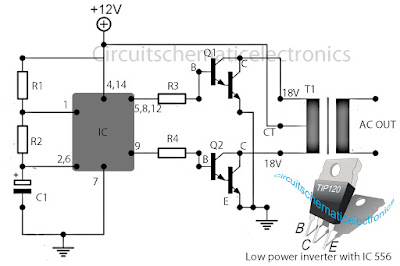
Low power inverter schematic are only use 9 components , one of which IC 556 , TIP120 NPN Darlington transistor.And turns 10 to 16 Vdc into 60 HZ, output 115 V square-wave power to operate ac equipment up to 25 W. In the circuit first ic originally hires as a timer chip m for stabilizatiom oscilator with components R1 and C1 setting frequency oscilator. Then the two transistor driver, drive the transformer push-pull fashion, When one transistor is biased on , the other circuit cut-off . The transformer is a 120V/18Vct unit that is connected backwards, so that it steps the voltage up rather than down. Oscilator circuit operates from about 4 to 16 V for stable output.
Part List :
R1 = 1K
R2 = 12K
R3 = 1K
R4 = 1/4W
C1 = 1uF
IC = 556
Q1 = TIP120
Q2 = TIP120
T1 = 120V 18VCT
Friday, December 27, 2013
Running Disco Light with IC 4017

Inverter 5000W with PWM Pulse Width Modulator
 |
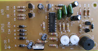
| Schematic Inverter 5000W with PWM (Pulse Width Modulator) |
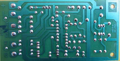 |
| Layout PCB Inverter 5000W with PWM (Pulse Width Modulator) |
below is the output power settings that can be issued by this inverter:
DC voltage and Transformer "T2" winding recommendation:
Winding Power Supply
12VDC 750W P: 24V "12-0-12" / S: 220V
1500W 24VDC P: 48V "24-0-24" / S: 220V
2250w 36VDC P: 72V "36-0-36" / S: 220V
3000w 48VDC P: 96V "48-0-48" / S: 220V
3750w 60VDC P: 120V "60-0-60" / S: 220V
4500w 72VDC P: 144V "72-0-72" / S: 220V
5250w 84VDC P: 168V "84-0-84" / S: 220V
Transformer used is the transformer CT
R1 serves to regulate the voltage to 220v inverter
R2 serves to regulate the inverter output frequency of 50 or 60 Hz (as appropriate)

Schematic Audio Amplifier with IC AN214

Tuesday, December 24, 2013
65W Power Amplifier Circuits with HEXFET
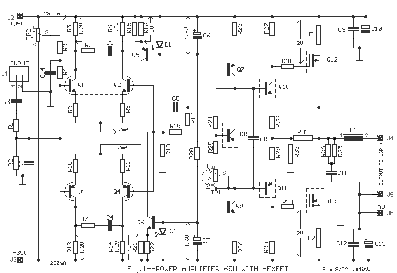 65W Power Amplifier Circuits with HEXFET
All the transistors that are acclimated in the ambit are simple and they abide in big clearings in the market. The pairs of cogwheel amplifiers Q1-2 and Q3-4 should be akin amid them and abreast the one in the other. Appropriately you can buy abundant transistors of types BC550C and BC560C, and with a multimeter you bout amid them creating pairs with aforementioned characteristics, ensuring appropriately compatible behavior in the temperature changes etc. Networks RC from the R7/C3 and R12/C4 abatement the bandwidth of cogwheel amplifiers and ability amplifier in the 6.5MHZ. Resistors R8-9-10-11 action as bounded acknowledgment in the cogwheel amplifiers convalescent the linearity. The cogwheel amplifiers are supplied with connected accepted from him accepted sources Q5 and Q6. The bent of accepted sources becomes from the aggregate of diodes LED D1, D2 and R20.
This becomes because the aggregate transistor/LED ensures big thermic stability, for this acumen should they are in actual abreast ambit [1]. With the TR1 trimmer we adapt the bent accepted of achievement ability stage. For this acumen Q8 should acquisition itself on the heatsink so that it ensures thermic adherence in the bias, so that it does not change with the temperature changes. The resistors R32-33 appearance a bounded acknowledgment bronchus in the achievement stage, because this functions as voltage amplifier.
With the TR1, R3-4, C14 we adapt the amplifier achievement DC account voltage, abreast in the zero. The transistors Q8-10-11-12-13, [Fig.1] should are placed on heatsink, abacus amid the transistors and the heatsink of acceptable affection leaves mica and ointment. Inductor L1 is constituted by 6 coils of cloistral cupreous wire of bore 1.5mm, with centralized inductor bore of 16mm
Stereo tone control with loudness and filter
Tone control circuit is used to adjust the tones before entering the amplifier. Tone control over equipped with a loudness and filter directly without using the switch to disconnected or connected. Part of his filter that is C1 and R1 from ground to input , and for his loudness on the R4 and C3 are connected to the input and then go to VR1. C2 and R3 go from ground to the input . After the input is set by volume or VR1 then procesed again by treebel ie C8 , R13 , R14 , and VR2 . Bass on R10 , R11, R12 , C7 ,C8 , and VR3. For supply voltages has been given a stabilization in Q3. See schematic below :
  |
| Click to view larger |
Part list :
R1 = 100K
R2 = 50K trim
R3 = 22K
R4 = 15K
R5 = 1K
R6 = 4K7
R7 = 330K
R8 = 330K
R9 = 3K3
R10= 5K6
R11= 8K2
R12= 5K6
R13= 1K
R14= 1K
R15= 50K TRIM
R16= 50K TRIM
R17= 330K
R18= 4K7
R19= 47K
R20= 1K
R21= 4K7
R22= 2K2
R23= 100R
R24= 22K
C1 = 15n
C2 = 15n
C3 = 560p
C4 = 4u7
C5 = 33u
C6 = 4n7
C7 = 39n
C8 = 39n
C9 = 4u7
C10=4u7
C11=470u
C12=100u
Q1 = C1815
Q2 = C828
D1 = Green Led
This tone control is suitable with 150W OCL power amplifier type 036.But the schematic is mono, if you need a stereo tone control you must duplicate the components and circuit.
 |
| Installation the stereo tone control |
Audio Amplifer Circuit 230W With MOSFET IRFP240 9240
 Audio Amplifer Circuit 230W With MOSFET IRFP240,9240
Here is simple LED-power audio amplifier ambit with MOSFET amplifier TL071C and 2 may be up to 45 W into 8 ohms. For MOSFET IRFP240 and IRFP9240 are acclimated assurance with accessory can now be these modification.
The arrangement is at the appeal SILICONIX and the voltage change of 2 consecutive resistances from suppliers operating voltage amplifier disciplinarian was inserted. MOSFET charge be army on at atomic one condenser 1K / W.
Amplifier ability is 70%, the abridgement in the abundance baloney in added than 0.2% at 20 Hz at 8 ohms and 10W. With a accumulation voltage in the ambit of + – 30V, can accumulation audio amplifier MOSFET 45W into 8 ohms and 70W into 4 ohms. Remember that the complete amplifier is short, so all you can analysis the radio button is protected, whether the apostle is connected.
Monday, December 23, 2013
FM Radio Transmitter schematic with pcb
For those of you like / love to talk in the air can assemble this simple circuit that can be received by the radio receiver to within a few hundred feet. The voice that issues by this circuit at all clear without rustling. Can also be used to link communications over the air using this radio transmitter, provided that other person also had the same circuit.

This PCB design :

Description :
Resistor
R1__________________1K
R2__________________18K
R3__________________82K
R4__________________1K2
R5__________________5K6
R6__________________39K
R7__________________18K
R8__________________68K
R9__________________470R
R10_________________100R
R11_________________50K
XTal
Q1__________________ Crystal according to the desired frequency
Inductor
L1__________________10uH
Capacitor
C1__________________10uF
C2__________________30uF
C3__________________20uF
C4__________________47uF
Transistor
Tr1_________________2SB175
Tr2_________________2SB175
Tr3_________________2SB178
Antenna
X1-1________________10-20 meters
Connector
X2-1________________Ground
X2-2________________VCC 9-12 Volts DC
X3-1________________Input
X3-2________________Ground
Sunday, December 22, 2013
Video Signal Amplifier Using with LH0024
The construction of the circuit has been increased to highlight and amplify video signals for further frequencies on image clarity.
Video Signal Amplifier Circuit diagram

Terminology
LH0024 – IC small signal IC designed for general purpose switching and amplification due to its low voltage, low voltage and three different win the election 1N4148 – silicon small signal diode planar epitaxial used for fast switching applications with a reverse voltage of 100 V and forward current of 150 mA
Circuit Explanation
In a video output signal is the high rate of frames selected for amplification of producing a finer. This is possible by placing the track between the video device and the reception lobby, where the video port of the television receiver is inserted. The construction is done simply by exploiting the operation of three transistors instead of IC and other supporting elements.
An isolator operating in the first phase of the Q1, which provides an interface for input impedance. Q2 manage the second phase, which leads to the common base configuration. In this phase, determine the earnings TR2 250 ohms cutting the lawn. To adjust TR2, it must be placed where an output voltage of 1 Vp-p is present, with a load of 75 ohms. The frequency response is regulated by a combination of R6, C3, and 500 ohms TR1. An output buffer is completed by Q3 of the third phase which provides an airline pilot with 75 ohms. The range of the circuit is stabilized with 12 V and 50 mA.
Friday, December 20, 2013
Creating a stereo amplifier with TDA2003

Here I make a stereo power amplifier with IC TDA2003, but actually i made it with 2 IC , so that a stereo amplifier . Construction is very simple and easy. I only need 2 TDA2003 mono amplifier circuit , and then combined into one.Then the transformer , the transformer that i use here is the transformer 10A , so that the power released is greater. Grid power amplifier using the former from the box 10A adaptor , :-) decent can still be used . To view the location of components inside the box , see below :


 |
| Top |
 |
| Right |
 |
| Top - Right |
Wow .,.,this amplifier is very good if using a transformer 10A, issued no buzzing sound , and strong for high bass , just nice deehh..,.,,.,.
Simple Inverter circuit with IC556 timer chip
This circuit is low power inverter , in this circuit only save a few components, about 9 parts. Voltage input from 10 volt to 16 volt DC into 60-Hz. And then voltage will be raised to about 115 V with power 25 W. The first section of IC 556 timer chip is wire as an astable oscilator with R2 and C1 setting the frequncy. The output is available at IC 556 pin 5. The second section is wired as a phase inverter. That output is available at IC 556 pin 9.
Schematic low inverter below :

Thursday, December 19, 2013
LED Circuit with Timer 555

Wednesday, November 20, 2013
16 × 2 LCD Volt Meter Ampere Meter With PIC
 |
| Volt meters & ampere meter with PIC |
Tuesday, November 19, 2013
Power Amplifier Circuit 2 x 20 W stereo with IC AN7156N
This circuit operate with IC AN7156N . You just can use this IC , because havnt similarity it. In this Circuit have 2 input IN R and IN L and have Output R and L . Voltage supply require 15 V , minimum voltage 9 V and maximum voltage 24V . And the voltage must DC voltage , and better the DC voltage filtering .
Maximum Output for 1 speaker 25 W , so this circuit have maximum output 2 X 25 W with minimum impedance 4 ohm. See this circuit schematic below :
 |
| Click image to view enlarge |
Car Amplifier with IC LA4445
This circuit using IC LA4445 , this is stereo amplifier with power output 2 X 18 Watt, with this circuit you can use to car amplifier or to other elctronics device. Speaker use woofer with impedance 4 Ohm with power up to 20 Watt. Minimum voltagte require 10 Volt and maximum voltage 18 volt.see schematic below :

Monday, November 18, 2013
Power amplifier compatible with TV audio

