Wednesday, January 22, 2014
The Alpine Car Stereo
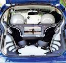 Alpine car stereo and electronics, founded in 1978, is a world leader in the industry of high performance mobile electronics. They specialize in mobile multimedia, an integrated system approach incorporating digital entertainment, security and navigation products for the mobile entertainment.
 To grasp what the Alpine car stereo Mobile Multimedia is, take a look at the IVA-D901 Alpine car stereo Mobile Multimedia Station/CD/DVD Receiver/Ai-NET Controller.
Saturday, January 11, 2014
Sony Car Stereo
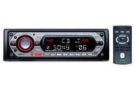 |
| Sony car stereo Xplod Series |
Wednesday, December 25, 2013
200W Stereo High Power Amplifier LM3886
 The LM3886 circuit is in a non-inverted configuration, so the input impedance is determined by the input resistor R1, i.e. 47k. The 680 ohm and 470pF resistor capacitor filter network is used to filter out the high frequency noise at the RCA input. The 220pF C4 and C8 capacitors are used to shot out the high frequency noise at the LM3886 input pins.
 |
| LM3886 Power Amplifier Schematics |
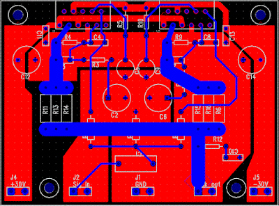
The PCB is designed in a way that the power ground is separated from the signal ground, as you can see from the below layout. The signal ground is located in the middle and surrounded by the power ground. There is a thin trace near C5 connecting them. The PCB layout is done by using PADS PowerPCB 5.0. I think it is a powerful layout software.
Amplifier Printed Circuit Board (PCB)
 |
| Amplifier Printed Circuit Board Bottom |
 |
| Amplifier Printed Circuit Board Top |
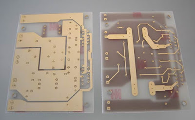 |
| Amplifier Printed Circuit Board |
The power supply used is a regulated power supply. I used 10000uF per rail before the LT1083 regulator. After the regulator, I have 100uF on the regulator board. The advantage of using regulator is that the power supply ripple voltage is removed. If power regulation is not used, I can hear very little 50/100Hz hum from the speaker.
The high current MUR860 diode is used to ensure high current flow. The voltage regulator used is LT1083, it can provide about 8A of current. Transformer used here is a 500VA 2x 25V. The power supply is then regulated by 2 LT1083, after the regulation, the voltage is 30V.
 |
| Power Supply Recomended |
The sound of this amplifier is similar to my LM3875 amplifier, which is very clean and detail. It has no hum, no hiss and no noise. Compared to the LM3875 Gainclone, this amp can deliver twice the power to my 4-ohm speaker, and it improves the dynamics and bass punch a lot.
Source :http://www.shine7.com/audio/pa100.htm
Tuesday, December 24, 2013
Stereo tone control with loudness and filter
Tone control circuit is used to adjust the tones before entering the amplifier. Tone control over equipped with a loudness and filter directly without using the switch to disconnected or connected. Part of his filter that is C1 and R1 from ground to input , and for his loudness on the R4 and C3 are connected to the input and then go to VR1. C2 and R3 go from ground to the input . After the input is set by volume or VR1 then procesed again by treebel ie C8 , R13 , R14 , and VR2 . Bass on R10 , R11, R12 , C7 ,C8 , and VR3. For supply voltages has been given a stabilization in Q3. See schematic below :
  |
| Click to view larger |
Part list :
R1 = 100K
R2 = 50K trim
R3 = 22K
R4 = 15K
R5 = 1K
R6 = 4K7
R7 = 330K
R8 = 330K
R9 = 3K3
R10= 5K6
R11= 8K2
R12= 5K6
R13= 1K
R14= 1K
R15= 50K TRIM
R16= 50K TRIM
R17= 330K
R18= 4K7
R19= 47K
R20= 1K
R21= 4K7
R22= 2K2
R23= 100R
R24= 22K
C1 = 15n
C2 = 15n
C3 = 560p
C4 = 4u7
C5 = 33u
C6 = 4n7
C7 = 39n
C8 = 39n
C9 = 4u7
C10=4u7
C11=470u
C12=100u
Q1 = C1815
Q2 = C828
D1 = Green Led
This tone control is suitable with 150W OCL power amplifier type 036.But the schematic is mono, if you need a stereo tone control you must duplicate the components and circuit.
 |
| Installation the stereo tone control |
Friday, December 20, 2013
Creating a stereo amplifier with TDA2003

Here I make a stereo power amplifier with IC TDA2003, but actually i made it with 2 IC , so that a stereo amplifier . Construction is very simple and easy. I only need 2 TDA2003 mono amplifier circuit , and then combined into one.Then the transformer , the transformer that i use here is the transformer 10A , so that the power released is greater. Grid power amplifier using the former from the box 10A adaptor , :-) decent can still be used . To view the location of components inside the box , see below :


 |
| Top |
 |
| Right |
 |
| Top - Right |
Wow .,.,this amplifier is very good if using a transformer 10A, issued no buzzing sound , and strong for high bass , just nice deehh..,.,,.,.
Friday, November 22, 2013
Stereo 30W STK ICs amplifier circuit
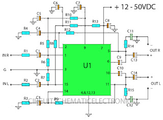
Component List :This amplifier circuit based on IC STK ic used in which the manifold. And on this circuit ic STK has many similarities, you can use the STK430 ICs, 433, 435, 437, 439, 441, 443, 4332, 4352, 4362, 4372, 4392. Between the specify type IC STK, which has the excellent performance is STK433 and STK443 because it has output, and high amperage, and voltage problems Suplly but I chose IC STK443 because maximum voltage up to 70 volts, compared with the others that just under 60 volts. For a list of components can seen below.
Resistor
R1_____1KΩ
R2_____1KΩ
R3_____120Ω
R4_____120Ω
R5_____330KΩ
R6_____22KΩ
R7_____22KΩ
R8_____330KΩ
R9_____12KΩ
R10____220KΩ
R11____220KΩ
R12____12KΩ
R13____100Ω
R14____4Ω7
R15____4Ω7
Capacitor
C1_____4µ7F
C2_____4µ7F
C3_____220µF
C4_____220µF
C5_____100µF
C6_____100µF
C7_____220µF
C8_____100µF
C9_____47µF
C10____47µF
C11____0.1µF
C12____0.1µF
C13____2200µF
C14____2000µF
**Orange on symbol capacitor is plus Elco**
IC
U1_____STK430 , STK433 , STK435 , STK437 , STK439 , STK441 , STK443 , STK4332 , STK4352 , STK4362 , STK4372 , STK4392.
Wednesday, November 20, 2013
2 X 30 Watt stereo amplifier by TDA1510
This power amplifier can use IC TDA1510 or TDA1515, minimum voltage require 6 volt and maximum voltage require 18 Volt, Voltage with DC supply voltage.Power output 2x 30 Watt stereo amplifier , with 2 ohms impedance , its is low impedance . You can use the fullrange or woofer speakers. see schematic below :

Tuesday, November 19, 2013
Power Amplifier Circuit 2 x 20 W stereo with IC AN7156N
This circuit operate with IC AN7156N . You just can use this IC , because havnt similarity it. In this Circuit have 2 input IN R and IN L and have Output R and L . Voltage supply require 15 V , minimum voltage 9 V and maximum voltage 24V . And the voltage must DC voltage , and better the DC voltage filtering .
Maximum Output for 1 speaker 25 W , so this circuit have maximum output 2 X 25 W with minimum impedance 4 ohm. See this circuit schematic below :
 |
| Click image to view enlarge |
Saturday, November 2, 2013
KA2211 Stereo audio power amplifier
 This amplifier circuit has a stereo output with a power output of 2 x 5.8 Watt with impedance 4. The frequency response from 30Hz up to 20kHz. Amplifier circuit based on IC KA2211 and supported several other components. Minimum supply voltage of 10 Volt to 18 Volt.
Below is schematic power amplifier with IC KA2211 suitable for home power amplifier.
 |
| Home amplifier schematics with IC KA2211 |
Tuesday, October 29, 2013
KA2211 Stereo audio power amplifier
This amplifier circuit has a stereo output with a power output of 2 x 5.8 Watt with impedance 4. The frequency response from 30Hz up to 20kHz. Amplifier circuit based on IC KA2211 and supported several other components. Minimum supply voltage of 10 Volt to 18 Volt.Below is schematic power amplifier with IC KA2211 suitable for home power amplifier.
|
| Home amplifier schematics with IC KA2211 |
Saturday, October 26, 2013
6 Watt stereo power amplifier schematic
Basiccally,this amplifier works with the IC, which is where ic is associated with several other components in the supply and use DC voltage, which corresponds to the needs of IC above course on the circuit schematic. For IC , stands intregated circuit used is ic LM379 which has a maximum 6 Watt stereo output. This IC manufactered by NS and with SDIP-14 package. While other components needed in the circuit schematic , you can see components of the list below.

Resistor
R1___________________2K
R2___________________2K
R3___________________33K
R4___________________33K
R5___________________1M
R6___________________1M
R7___________________10R 2W
R8___________________10R 2W
Capacitor
C1___________________4.7uF
C2___________________4.7uF
C3___________________470uF
C4___________________470uF
C5___________________470uF
C6___________________100n
C7___________________100n
IC
IC1___________________LM379
Tuesday, October 22, 2013
Car Stereo Audio Amplifier with TDA1553CQ Circuit Diagram
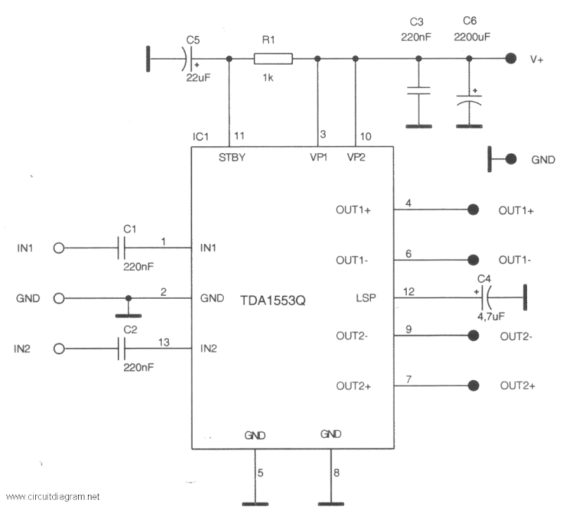 Car Stereo Audio Amplifier with TDA1553CQ Circuit Diagram
This is a stereo audio amplifier for your car. The ambit is powered by a distinct IC TDA1553 with some alien components, this IC will handle your stereo car audio system.
The TDA1553CQ is a caked chip class-B achievement amplifier in a 13-lead artificial DIL-bent-SIL ability package. It contains 2×22 W amplifiers in BTL configuration. The accessory is primarily developed for car radio applications.
Special features of the device are:
3-state mode switch
· standby: low supply current (<100>
Loudspeaker protection
When a short-circuit to ground occurs, which forces a DC voltage across the loudspeaker of >= V, a built-in protection circuit becomes active and limits the DC voltage across the loudspeaker to <= V. Pin 12 detects the status of the protection circuit (e.g. for diagnostic purposes).
Short-circuit protection
If any output is short-circuited to ground during the standby mode, it becomes impossible to switch the circuit to the mute or operating condition. In this event the supply current will be limited to a few milliamps.
Saturday, October 5, 2013
TDA2004 stereo bridge audio amplifier


Sunday, September 29, 2013
3 Watt stereo amplifier circuit
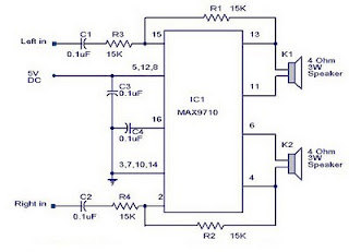 |
| 3 Watt stereo amplifier circuit |
Saturday, September 21, 2013
120W Stereo Amplifier using STK4241V
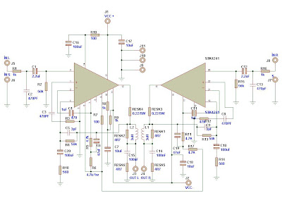
This amplifier circuit is ideal for audio devices for home supply. STK4241V amplifier specifications might lead one to believe that you can use supply voltages of ± 78V. With zero input signal (and therefore no way out) I could, but I would not recommend anything better than ± 45V 8-ohm loads, if expected, although ± 54V will be fine if you can provide a good heat sink.
Friday, September 20, 2013
Car Amplifier Circuit 2 x 30 W stereo
This circuit use the IC AN7166 . On circuit have an advantage is very loud sound , although only 30W this circuit is like a 100 W transistor power amplifier. Its so good circuit with IC AN7166 . This circuit require minimum voltage 12 V and Maximum voltage 24 volt , I recomended voltage for this circuit is 18 volt. And use the battery supply current 5 Ampere. Maximum power output of one speaker 30 W with impedance 4 Ohm.
See this circuit schematic below :
 |
| Click image to view large |
Capacitor thats connect legs IC 4 and 3 is 1 nF . And capacitor thats connect legs IC 9 and 3 is 1 nF. For the input capacitor at 1 uF ( L and R ) for output capacitor at 1000uF with voltage 50 V or higher.
Tuesday, September 17, 2013
STK465 Stereo Power Amplifier 2x30W
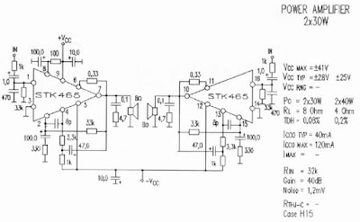
R1= 1K C1= 1uF/35V R2= 3,3K C2= 470pF R3= 100 C3 = 100uF/60V R4 = 330 C4 = 100uF/60V R5 = 3,3K C5 = 10uF/60V R6 = 1K C6 = 47uF/60V R7 = 0,33 C7 = 8,2pF R8 = 33К C8 = 0,1uF R9 = 4,7 C9 = 1uF/35V R10 = 1К C10 = 470pF R11 = 3,3К C11 = 100uF/60V R12 = 100 C12 = 100uF/60V R13 = 330 C13 = 10uF/60V R14 = 3,3К C14 = 47uF/60V R15 = 1К C15 = 8,2pF R16 = 0,33 C16 = 0,1uF R17 = 33К R18 = 4,7 IC1 = STK465 LS1 = Speaker 40W 8 or 4 Ohm
Sunday, September 15, 2013
Stereo Amplifier Circuit with IC AN7142
 |
| This is schematic circuit and i design in simple circuit. Click to view Enlarge |
Stereo Low power audio amplifier
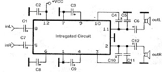
C1 = 1uF
C2 = 100uF
C3 = 100uF
C4 = 100uF
C5 = 0.1uF
C6 = 470uF
C8 = 100uF
C10 = 100uF
C12 = 470uF
Stereo Circuit Schematic of The ADAU1592 Audio Power Amplifier
