Showing posts with label tone. Show all posts
Showing posts with label tone. Show all posts
Saturday, January 18, 2014
Reducing Treble tone circuit
Treble reducer circuit above is an example of a simple circuit and is suitable to be used as experimental material and analysis of the workings of the circuit.

As I mentioned earlier the bass reducer series, this series actually has the same working principles with a series of bass reducer. Where these circuits utilize capacitors nature of the charge and discharge. The difference of the damping function obtained from the difference of the capacitor. If the series bass reducer series capacitors are mounted on the op-amp input lines, while in this treble reducer series capacitors are mounted parallel with the strengthening of the op-amp prisoners. Installation of this circuit has a parallel in the work analysis in contrast with the installation of the series on a series of bass reducer. The difference is that the installation of the series, so we URLs that are easy to understand how a wire working capacitors for high frequency signal, so with high frekuesni so automatic signal to be passed to the output terminal by a capacitor. But if we put a parallel between the output capacitor with the terminals, then automatically because the capacitor is considered as a wire so the voltage on the capacitor is near 0 volts, so the output voltage will also follow the voltage on the capacitor because they connect parallel. As with the low frequency signal, the capacitor is considered open and makes voltage wire that fell to him is to approach the input voltage. To understand how the capacitor can be regarded as a wire or an open switch I mentioned in my post about the working principles of capacitors and a series of bass reducer.
Indeed, when examined in detail, not only the capacitors that play a role here but the component resistors and op-amp also affect. But I can confirm that the main function is performed by a capacitor reduction. Series resistors are intended to be installed that will flow into the capacitor can be adjusted so that it influences the charge and discharge the capacitor will make the appropriate damping.
Take a look at the picture above the treble reducer circuit and also the image output signal. There are two function generator as input and has a signal with different frequencies. The first signal of amplitude 1 volt and low frequencies, the two signals with an amplitude of 1 volt and with high frequency. At the time of our input select switch position to the relationship with the input low frequency signal, the signal output will be nearly equal to the input signal such as no change. Whereas if we switch position to link high-frequency input signal then the output signal amplitude will be damped near 0 volts.
Example treble reducer circuit is very simple and can you develop more in accordance with the desires and your needs. At least with understanding the working principle of this circuit we can apply a time when we are required to perform the function of damping trebele.

Tuesday, December 24, 2013
Stereo tone control with loudness and filter
Tone control circuit is used to adjust the tones before entering the amplifier. Tone control over equipped with a loudness and filter directly without using the switch to disconnected or connected. Part of his filter that is C1 and R1 from ground to input , and for his loudness on the R4 and C3 are connected to the input and then go to VR1. C2 and R3 go from ground to the input . After the input is set by volume or VR1 then procesed again by treebel ie C8 , R13 , R14 , and VR2 . Bass on R10 , R11, R12 , C7 ,C8 , and VR3. For supply voltages has been given a stabilization in Q3. See schematic below :
  |
| Click to view larger |
Part list :
R1 = 100K
R2 = 50K trim
R3 = 22K
R4 = 15K
R5 = 1K
R6 = 4K7
R7 = 330K
R8 = 330K
R9 = 3K3
R10= 5K6
R11= 8K2
R12= 5K6
R13= 1K
R14= 1K
R15= 50K TRIM
R16= 50K TRIM
R17= 330K
R18= 4K7
R19= 47K
R20= 1K
R21= 4K7
R22= 2K2
R23= 100R
R24= 22K
C1 = 15n
C2 = 15n
C3 = 560p
C4 = 4u7
C5 = 33u
C6 = 4n7
C7 = 39n
C8 = 39n
C9 = 4u7
C10=4u7
C11=470u
C12=100u
Q1 = C1815
Q2 = C828
D1 = Green Led
This tone control is suitable with 150W OCL power amplifier type 036.But the schematic is mono, if you need a stereo tone control you must duplicate the components and circuit.
 |
| Installation the stereo tone control |
Saturday, December 14, 2013
3 Band Tone Control Circuit
3 Band Tone Control circuit uses an op-amp as an amplifier end. Tone Control circuit is a regulator of tone bass, midrange and treble or 3 band called because it can set the three tones. Filter circuit is applied to the series of "Tone Control 3 band" This type baxandal like the title of this article.
Results filtering regulator tone or tone control baxandal type is good, because there is no signal level is wasted directly into the ground. Range frequency tones generated from Tone Control 3 band was determined by the configuration of the R and C of the filter section baxandal. As an amplifier on Tone Control The set of three band use traditional IC LF351 has slewrate high and high input impedance. For more details, series 3 Band Tone Control as follows.
Figure Series 3 Band Tone Control

3 Band Tone Control circuit above using LF351 Op-Amp is used to strengthen the signal after filtering by the filter process baxandal. Level tone Bass, Midrange and Treble settings are determined by potensio R1, R2 and R3. Frequency filter in the circuit above baxandal to 50 Hz bass tone, tone Midrange 1 KHz and 10 KHz for Treble tone.
Wednesday, October 23, 2013
Tone Control Circuit Designed Using LM833
Using LM833 can be designed a very simple tone control circuit using few external components .For this Lm833 ton control circuit can be used almost any type of operational amplifier if it have high input impedance .The LM833 is a is a dual general purpose operational amplifier designed with particular emphasis on performance in audio systems.
Tone Control Circuit Diagram
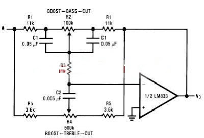
The ton control from this circuit is based on this operational amplifier from National Semiconductor and two RC filters ( low pass and high pass ) .Using the formula presented bellow we can modify the frequency of the tone control circuit - the cut off frequency of RC filters (low pass and high pass )lm833 tone control formula For the tone control circuit presented in this schematic the frequencies are : fL = 32 Hz, fLB = 320 Hz and fH =11 kHz, fHB = 1.1 kHz.
Tone Control Circuit Diagram
The ton control from this circuit is based on this operational amplifier from National Semiconductor and two RC filters ( low pass and high pass ) .Using the formula presented bellow we can modify the frequency of the tone control circuit - the cut off frequency of RC filters (low pass and high pass )lm833 tone control formula For the tone control circuit presented in this schematic the frequencies are : fL = 32 Hz, fLB = 320 Hz and fH =11 kHz, fHB = 1.1 kHz.
Subscribe to:
Posts (Atom)