Tuesday, December 24, 2013
Stereo tone control with loudness and filter
Tone control circuit is used to adjust the tones before entering the amplifier. Tone control over equipped with a loudness and filter directly without using the switch to disconnected or connected. Part of his filter that is C1 and R1 from ground to input , and for his loudness on the R4 and C3 are connected to the input and then go to VR1. C2 and R3 go from ground to the input . After the input is set by volume or VR1 then procesed again by treebel ie C8 , R13 , R14 , and VR2 . Bass on R10 , R11, R12 , C7 ,C8 , and VR3. For supply voltages has been given a stabilization in Q3. See schematic below :
  |
| Click to view larger |
Part list :
R1 = 100K
R2 = 50K trim
R3 = 22K
R4 = 15K
R5 = 1K
R6 = 4K7
R7 = 330K
R8 = 330K
R9 = 3K3
R10= 5K6
R11= 8K2
R12= 5K6
R13= 1K
R14= 1K
R15= 50K TRIM
R16= 50K TRIM
R17= 330K
R18= 4K7
R19= 47K
R20= 1K
R21= 4K7
R22= 2K2
R23= 100R
R24= 22K
C1 = 15n
C2 = 15n
C3 = 560p
C4 = 4u7
C5 = 33u
C6 = 4n7
C7 = 39n
C8 = 39n
C9 = 4u7
C10=4u7
C11=470u
C12=100u
Q1 = C1815
Q2 = C828
D1 = Green Led
This tone control is suitable with 150W OCL power amplifier type 036.But the schematic is mono, if you need a stereo tone control you must duplicate the components and circuit.
 |
| Installation the stereo tone control |

Wednesday, December 18, 2013
8 Relay Control Circuit
R1-8=4.7 Kohms T1-8= BD139 (R1-8=15 Kohms if T1-8=BD679)
RL1-8=6V-24V dc Relay D1-8=1N4148

Tuesday, December 17, 2013
TV Remote Control Jammer
TV Remote Control Jammer Circuit diagram:

There are so many IR emitters that we cannot put a generic number on the circuit to represent the type of diode. Some types include: CY85G, LD271, CQY37N (45¢), INF3850, INF3880, INF3940 (30¢). The current through the IR LED is limited to 100mA by the inclusion of the two 1N4148 diodes, as these form a constant-current arrangement when combined with the transistor and 5R6 resistor.
Monday, December 16, 2013
Photo Sensor Control Relay
Photo Sensor Control Relay Circuit Diagram

Saturday, December 14, 2013
3 Band Tone Control Circuit
Figure Series 3 Band Tone Control

Saturday, November 16, 2013
Fan control temperature using sensor LM35

Basic circuit of the LM35 are made to control the fan is either used on amplifier that requires automatic cooling. Its use on power amplifier circuit above and only requires DC fan. From basic sensors based on ic and amplifier op-amp is added again to the transistor Q1 to drive the fan.
Friday, November 8, 2013
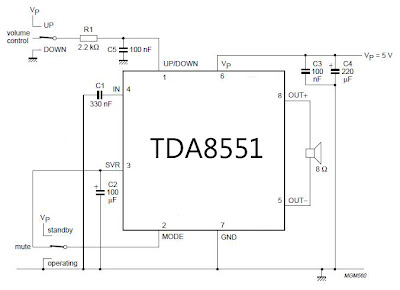
Low Power Amplifier with digital volume control
Techniques for adjusting the volume in this series has been provided with a pin path control that is controlled by providing an input voltage VCC and GND. The series is also equipped with a selector mute, standby and operating.
 |
| Mini amplifier with digital volume control schematics |
Sunday, November 3, 2013
Low Power Amplifier with digital volume control
Techniques for adjusting the volume in this series has been provided with a pin path control that is controlled by providing an input voltage VCC and GND. The series is also equipped with a selector mute, standby and operating.
|
| Mini amplifier with digital volume control schematics |
Friday, November 1, 2013
IR Remote Control Extender Mark 2

Notes:
The main difference between this version and the previous circuit, is that this design uses a commercially available Infra Red module. This module, part number IR1 is available from Harrison Electronics in the UK. The IR module contains a built in photo diode, amplifier circuit and buffer and decoder. It is centerd on the common 38kHz carrier frequency that most IR controls use. The module removes most of the carrier allowing decoded pulses to pass to the appliance. Domestic TVs and VCRs use extra filtering is used to completely remove the carrier. The IR1 is packaged in a small aluminium case, the connections viewed from underneath are shown below:
Infra Red Module, IR1 Pinout
How It works:
The IR1 module (IC3) operates on 5 Volt dc. This is provided by the 7805 voltage regulator, IC1. Under quiescent (no IR signal) conditions the voltage on the output pin is high, around 5 volts dc. This needs to be inverted and buffered to drive the IR photo emitter LED, LED2. The buffering is provided by one gate (pins 2 & 3) of a hex invertor the CMOS 4049, IC2. The IR1 module can directly drive TTL logic,but a pull-up resistor, R4 is required to interface to CMOS ICs. This resistor ensures that the signal from a remote control will alternate between 0 and 5 volts. As TTL logic levels are slightly different from CMOS, the 3.3k resistor R4 is wired to the +5 volt supply line ensuring that the logic high signal will be 5 volts and not the TTL levels 3.3 volts. The resistor does not affect performance of the IR module, but DOES ensure that the module will correctly drive the CMOS buffer without instability.
The output from the 4049 pin 2 directly drives transistor Q1, the 10k resistor R1 limiting base current. LED1 is a RED LED, it will flicker to indicate when a signal from a remote control is received. Note that in this circuit, the carrier is still present, but at a reduced level, as well as the decoded IR signal. The CMOS 4049 and BC109C transistor will amplify both carrier and signal driving LED2 at a peak current of about 120 mA when a signal is received. If you try to measure this with a digital meter, it will read much less, probably around 30mA as the meter will measure the average DC value, not the peak current. Any equipment designed to work between 36 and 40kHz should work, any controls with carrier frequencies outside this limit will have reduced range, but should work. The exception here is that some satellite receivers have IR controls that use a higher modulated carrier of around 115KHz. At present, these DO NOT work with my circuit, however I am working on a Mark 3 version to re-introduce the carrier.
Parts List:
C1 100u 10V
C2 100n polyester
R1 10k
R2 1k
R3 33R 1W
R4 3k3
Q1 BC109C
IC1 LM7805
IC2 CMOS 4049B
IC3 IR1 module from Harrison Electronics See Last paragraph
LED1 Red LED (or any visible colour)
LED2 TIL38 or part YH70M from Maplin Electronics
Testing:
This circuit should not present too many problems. If it does not work, arm yourself with a multimeter and perform these checks. Check the power supply for 12 Volt dc. Check the regulator output for 5 volt dc. Check the input of the IR module and also Pin 1 of the 4049 IC for 5 volts dc. With no remote control the output at pin 2 should be zero volts. Using a remote control pin 2 will read 5 volts and the Red LED will flicker. Measuring current in series with the 12 volt supply should read about 11mA quiescent, and about 40/50mA with an IR signal. If you still have problems measure the voltage between base and emitter of Q1. With no signal this should be zero volts, and rise to 0.6-0.7 volts dc with an IR signal. Any other problems, please email me, but please do the above tests first.
PCB Template:
Once again a PCB template has been kindly drafted for this project by Domenico.


The part number IR1 from Harrison Electronics is no longer available. They do supply an alternative IR decoder which I have tested and works. Other alternative Infrared decoders are shown below, note however that all DO NOT share the same pinout. I advise anyone making this to check the corresponding data sheets.
Vishay TSOP 1738
Vishay TSOP 1838
Radio Shack 276-0137
Sony SBX 1620-12
Sharp GP1U271R
Equipment Controlled Successfully:
If you have built this circuit and it works successfullt please let me know and I will build the list. Email details of the Manufacturer, device and remote control model number. The remote model number is usually on the front or back of the remote.
Technics CDP770 Remote: EUR64713
Wednesday, October 23, 2013
Tone Control Circuit Designed Using LM833
Tone Control Circuit Diagram
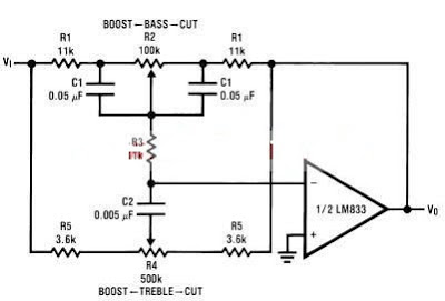
The ton control from this circuit is based on this operational amplifier from National Semiconductor and two RC filters ( low pass and high pass ) .Using the formula presented bellow we can modify the frequency of the tone control circuit - the cut off frequency of RC filters (low pass and high pass )lm833 tone control formula For the tone control circuit presented in this schematic the frequencies are : fL = 32 Hz, fLB = 320 Hz and fH =11 kHz, fHB = 1.1 kHz.
Tuesday, October 22, 2013
Loop Control Automatic Reversing Circuit Diagram
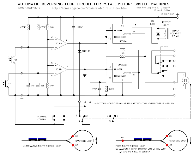 Loop Control Automatic Reversing Circuit Diagram
It is not the purpose of this folio to accommodate a abundant account of the ICs acclimated by this circuit. If you appetite added advice on this accountable amuse accredit to the Flip-Flop Made With A LM556 Timer Chip folio in the assorted circuits area of this armpit and additionally the Visible Light Photo Detector Circuits.
*The ambit uses the basal phototransistor detector ambit to faculty the position of a alternation that is abutting or is in the abandoning loop.
*Track polarity abandoning is not covered by this folio and will accept to be bent by the user.
Please Read Afore Using These Ambit Ideas
The explanations for the circuits on these pages cannot achievement to awning every bearings on every layout. For this acumen be able to do some experimenting to get the after-effects you want. This is abnormally accurate of circuits such as the "Across Track Infrared Detection" circuits and any added ambit that relies on added than absolute cyberbanking inputs, such as switches.
If you use any of these ambit ideas, ask your genitalia supplier for a archetype of the manufacturers abstracts bedding for any apparatus that you accept not acclimated before. These bedding accommodate a abundance of abstracts and ambit architecture advice that no cyberbanking or book commodity could access and will save time and conceivably accident to the apparatus themselves. These abstracts bedding can generally be begin on the web armpit of the accessory manufacturers.
Although the circuits are anatomic the pages are not meant to be abounding descriptions of anniversary ambit but rather as guides for adapting them for use by others. If you accept any questions or comments amuse accelerate them to the email abode on the Ambit Index page.
Thursday, October 17, 2013
IR Remote Control Tester

As I was developing my IR Extender Circuit, I needed to find a way of measuring the relative intensities of different Infra red light sources. This circuit is the result of my research. I have used a photodiode, SFH2030 as an infra red sensor. A MOSFET opamp, CA3140 is used in the differential mode to amplify the pulses of current from the photodiode. LED1 is an ordinary coloured led which will light when IR radiation is being received. The output of the opamp, pin 6 may be connected to a multimeter set to read DC volts. Infra red remote control strengths can be compared by the meter reading, the higher the reading, the stronger the infra red light. I aimed different remote control at the sensor from about 1 meter away when comparing results. For every microamp of current through the photodiode, about 1 volt is produced at the output. A 741 or LF351 will not work in this circuit. Although I have used a 12 volt power supply, a 9 volt battery will also work here.
Thursday, September 26, 2013
9 Sec Timer with LED Indication and Control Relay
9 Sec Timer with LED Indication and Control Relay Circuit Schematic

Saturday, September 14, 2013
IR Remote Control Extender Mark 1
This circuit is used to relay signals from an Infra Red remote control in one room to an IR controlled appliance in another room.
I have seen these devices advertised in magazines, they sell for around £40-£50 and use radio to transmit between receiver and transmitter. This version costs under £5 to make and uses a cable connection between receiver and transmitter. For example, if you have a bedroom TV set that is wired to the video or satellite in another room, then you can change channels on the remote satellite receiver using this circuit. The idea is that you take your remote control with you, aim at the IR remote control extender which is in the same room, and this will relay the IR signal and control the remote appliance for you. The circuit is displayed below:

1 SFH2030 Photodiode
1 TIL38 IR emitting diode
1 5mm Red LED
2 4.7M 1/4W resistors
1 1k 1/4W resistor
1 2.2k 1/4W resistor
1 27ohm 1/2W resistor
1 BC337 transistor
1 CA3140 MOSFET opamp
The CA31340 is available in the US from Electronix Express, part number N103140.
Circuit Advantages
The advantage of this design against similar designs is that there are no adjustments to make or set-up procedures. However care should be taken to avoid ambient light reaching the photodiode. A dayligt filter type (black in colour) is recommended. Bellwire or speaker cable may be used to remotely site the IR emitting diode, since this design uses low output impedance and will not pick up noise. Some systems require coaxial cable which is expensive and bulky. The wireless variety of remote control extenders need two power supplies, here one is used and being radio are inevitably EM noise pollution. A visual indication of the unit receiving an Infra Red signal is provided by LED1. This is an ordinary coloured LED, I used orange but any colour will do. You will see LED1 flash at a rate of 4 - 40Hz when a remote control button is pressed. LED0 is an Infra Red Emitter Diode, this is remotely wired in the room with the appliance to be controlled. I used the type SFH487 which has a peak wavelength of 880nm. This is available in the UK from Maplin Electronics, order code CY88V. Most IR remote controls operate at slightly different wavelengths, between the range of 850 - 950nm. If you cannot obtain the SFH487 then any IR emitter diode that has an output in the above range should work.
About IR Remote Controls
As previously stated IR remote controls use wavelengths between 850 - 950nm. At this short wavelength, the light is invisible to the human eye, but a domestic camcorder can actually view this portion of the electromagnetic spectrum. Viewed with a camcorder, an IR LED appears to change brightness. All remote controls use an encoded series of pulses, of which there are thousands of combinations. The light output intensity varies with each remote control, remotes working at 4.5V dc generally will provide a stronger light output than a 3V dc control. Also, as the photodiode in this project has a peak light response at 850nm, it will receive a stronger signal from controls operating closer to this wavelength. The photodiode will actually respond to IR wavelengths from 400nm to 1100nm, so all remote controls should be compatible.
Circuit Description
The receiver is built around a silicon photodiode, the SFH2030 available from Maplin, order code CY90X. This photodiode is very sensitive and will respond to a wide spectral range of IR frequencies. There is a small amount of infra red in direct sunlight, so make sure that the diode does not pick up direct sunlight. If this happens, LED1 will be constantly lit. There is a version of the SFH2030 that has a daylight filter built in, the SFH2030F order code CY91Y. A TIL100 will also give good results here. A photodiode produces minute pulses of current when exposed to infra red radiation. This current (around 1uA with the SFH2030 and a typical IR control used at a distance of 1 meter) is amplified by the CA3140 opamp. The opamp is configured as a current to voltage convertor, producing an output of about 4.7 volts per uA of input current. The photodiode, can be placed up to a meter or so away from the circuit. Screened cable is not necessary, as common mode signals (noise) will be rejected. It is essential to use a MOSFET input type here as there is zero output offset and negligible input offset current. A 741 or LF351 can not be used in this circuit. The output from the opamp is amplified by the BC337 operating in common emitter mode. As a MOSFET opamp IC is used, its quiescent voltage output is zero and this transistor and both LEDs will not be lit. The 1k resistor makes sure that the BC337 will fully saturate and at the same time limits base current to a safe level. Operating an IR remote control and pointing at the photodiode (SFH2030) will cause both LEDs to illuminate, you will only see the visable coloured LED (LED1) which will flicker. Remote controls use a system of pulse code modulation, so it is essential that the signal is not distorted by any significant amount. Direct coupling, and a high speed switching transistor avoid this problem.
Construction
No special PCB is required, I built my prototype on a small piece of Veroboard. The pinout for the CA3140 is shown below. Note that only the pins labeled in the schematic are used, pins 1, 5 and 8 are not used and left unconnected.

There is nothing to set-up or adjust in this circuit. The only thing to watch is that the emitting diode is pointing at the controlled device (video, CD player, etc). I found that the beam was quite directional. Also make sure that there is a direct line of sight involved. It will not work if a 5 foot spider plant gets in the way, for example. I had a usable range at 5 meters, but possibly more distance may be possible. As a check, place a dc volt meter across the 27 ohm resistor. It should read 0 volts, but around 2 or 3 volts when a remote control is aimed at the photodiode.
Specifications of Prototype
Having made my prototype, I ran a few tests :-
Current consumption 2mA standby 60mA operating ( with 12V supply)
2mA standby 85mA operating (with 15V supply)
IR receiver range < 1 meter
IR transmitter range > 5 meters
It is difficult to measure the IR transmitter range as this is dependent upon a number of factors. The type of infra red control used and its proximity to the receiving photodiode, the voltage supply, the wavelength and efficiency of the IR emitter and the sensitivity of the controlled appliance all affect overall performance.
In Use
The reception range of the IR remote control to the photodiode depends on the strength of the remote control, but I had a working range of a meter or so, this needs bearing in mind when placing the circuit. Its also a good idea to wire LED1, the coloured LED near to the photodiode, that way, you know that the unit has received a signal. The IR emitter has a larger range, I had no problems at 5 meters but may possibly work further distances. The emitting diodes are quite directional, so make sure it is aimed directly at the appliance to be controlled. The IR emitting diode is small and can be placed out of sight. I drilled a small hole above the door frame. The emitter diode leads were insulated and pushed through this hole, leaving an inch or so to adjust the angle and position of the LED. From a distance, the clear plastic lens of the diode could not be seen.
Final Comments and Fault Finding
To date this has proved to be one of the most popular circuits on my site. Of all the email I receive about this circuit, most problems relate to the Infra Red photo diode. You must make sure that this is pointed away from sunlight, or use a type with daylight filter, otherwise LED1 will be constantly lit, and LED0 will be in operation also. This will draw excessive current and in some case overheat the BC337. The main problem is when using a different photo diode to the SFH2030. Any other photo diode LED should work, but you need to know its operating wavelength range beforehand. This will generally be described in the manufacturers data sheet or possibly described if you order from an electronic component catalogue. With these last two points in mind, you should be rewarded with a useful and working circuit.
PCB Template
This has been very kindly drafted by Domenico from Italy. First the copper side:


The modification to the Mark 1 circuit below separtes IR handset signals from daylight and mains powered lighting. The 22n capacitor has a high impedance at 50/60Hz and daylight but allows a modulated signal to pass. The 2N2222 transistor is biased on under no signal, the BC337 will be fully off. A control signal will switch off and on the 2N2222 transistor at the modulation frequency of the control, which in turn controls the BC337. As this is a cleaner signal, the series resistor may be increased to 100ohms.
