Showing posts with label sensor. Show all posts
Showing posts with label sensor. Show all posts
Saturday, October 18, 2014
Simple Temperature Sensor Arduino
Hello people, it’s been a while since I have posted projects on this website. This semester was really busy, I didn’t have time to much else, but soon I will have my winter holiday (Here in south our summer holiday is from December to February).
Today I am going to show you how to build a simple temperature sensor using one LM35 Precision Temperature Sensor and Arduino, so you can hookup on your future projects. The circuit will send serial information about the temperature so you can use on your computer, change the code as you will. I’m planning to build a temperature sensor with max/min + clock + LCD, and when I get it done, I will post here.
Parts:
This is a quick and simple step. Just connect the 5V output from arduino to the 1st pin of the sensor, ground the 3rd pin and the 2nd one, you connect to the 0 Analog Input.
Down goes some pictures that may help you, click to enlarge:


Here is the Arduino Code, just upload it and check the Serial Communication Option.
You can also download the .pde HERE.
Anything just ask!
Source by : link
Today I am going to show you how to build a simple temperature sensor using one LM35 Precision Temperature Sensor and Arduino, so you can hookup on your future projects. The circuit will send serial information about the temperature so you can use on your computer, change the code as you will. I’m planning to build a temperature sensor with max/min + clock + LCD, and when I get it done, I will post here.
Parts:
- Arduino (You can use other microcontroller, but then you will need to change the code).
- LM35 Precision Centigrade Temperature Sensor, you can get from any electronic store. Here is the DATA SHEET.
- BreadBoard
This is a quick and simple step. Just connect the 5V output from arduino to the 1st pin of the sensor, ground the 3rd pin and the 2nd one, you connect to the 0 Analog Input.
Down goes some pictures that may help you, click to enlarge:
Here is the Arduino Code, just upload it and check the Serial Communication Option.
You can also download the .pde HERE.
/*
An open-source LM35DZ Temperature Sensor for Arduino. This project will be enhanced on a regular basis
(cc) by Daniel Spillere Andrade , http://www.danielandrade.net
http://creativecommons.org/license/cc-gpl
*/
int pin = 0; // analog pin
int tempc = 0,tempf=0; // temperature variables
int samples[8]; // variables to make a better precision
int maxi = -100,mini = 100; // to start max/min temperature
int i;
void setup()
{
Serial.begin(9600); // start serial communication
}
void loop()
{
for(i = 0;i< =7;i++){ // gets 8 samples of temperature
samples[i] = ( 5.0 * analogRead(pin) * 100.0) / 1024.0;
tempc = tempc + samples[i];
delay(1000);
}
tempc = tempc/8.0; // better precision
tempf = (tempc * 9)/ 5 + 32; // converts to fahrenheit
if(tempc > maxi) {maxi = tempc;} // set max temperature
if(tempc < mini) {mini = tempc;} // set min temperature
Serial.print(tempc,DEC);
Serial.print(" Celsius, ");
Serial.print(tempf,DEC);
Serial.print(" fahrenheit -> ");
Serial.print(maxi,DEC);
Serial.print(" Max, ");
Serial.print(mini,DEC);
Serial.println(" Min");
tempc = 0;
delay(1000); // delay before loop
}
Anything just ask!
Source by : link
Thursday, December 19, 2013
Simple Fluid Level Sensor
A very simple fluid lever sensor can be designed using this circuit diagram . This fluid level sensor electronic circuit project is very simple and can be used to control water pump or to activate /stop some devices when the sensor detects presence of water.
Simple Fluid Level Sensor Circuit diagram

This fluid level sensor circuit uses an ac sensing signal to eliminate electrolytic corrosion on the probes .The ac signal rectified is used to drive T1 transistor that drives a 12 volt relay , that can activate or stop some device . R2 resistor is used to modify the sensor sensitivity and can be replaced with a small variable resistor . MC104093B is a p channel quad 2 input NAND schmitt trigger and is pin to pin compatible with the CD4093 . The unused inputs must be tied to an appropriate voltage level , either ground or +12 volts (8,9,12 and 13) and the unused outputs must be left open (10 and 11) .
The circuit can be powered with an input voltage between 3 and 18 volts dc , but in our case the circuit use a 12 volts DC power source .
Simple Fluid Level Sensor Circuit diagram
The circuit can be powered with an input voltage between 3 and 18 volts dc , but in our case the circuit use a 12 volts DC power source .
Monday, December 16, 2013
Photo Sensor Control Relay
A photo or slightly activated relay normally open relay in the closed circuit / contact with the light. In this circuit, a photodiode is used to sense light. The photodiode has a high resistance in the absence of light strikes. The photodiode is connected to the reverse biased state. The only current flowing through it will be due to minority carriers.
Photo Sensor Control Relay Circuit Diagram
 When light falls on it, the minority current carriers in the wake of increasing the diode provides a low resistance. Because the voltage across the diode will not be sufficient to bias transistor Q1 and will be reset. Where there is darkness, the resistance increases photodiode and the voltage across it will be enough to move forward bias the transistor Q1 of the relay ON. The diode D2 is used as a diode to protect transistor switching transients produced relay. In this way, the load on the relay contacts can be switched on and off using light strikes the photodiode.
Photo Sensor Control Relay Circuit Diagram
Saturday, November 16, 2013
Fan control temperature using sensor LM35

Basic circuit of the LM35 are made to control the fan is either used on amplifier that requires automatic cooling. Its use on power amplifier circuit above and only requires DC fan. From basic sensors based on ic and amplifier op-amp is added again to the transistor Q1 to drive the fan.
Part List :
R1___220K
R2___100K
R3___3K3
R4___22K
R5___1M
R6___150R
R7___2K2
R8___33R 4W
C1___100pF
D1___1N4148
IC1__7915
IC2__TL072
IC3__LM35
F1___DC Fan 12V
Monday, November 11, 2013
Transistor Water Sensor Alarm
This water sensor alarm circuit diagram is designed using common electronic components. Thewater sensor alarm circuit may operate an active buzzer, to make a sound when is reached a certain level of water.
Transistor Water Sensor Alarm Circuit Diagram

Because water sensor and control circuit for buzzer are located on the same printed circuit board, indicator, together with 9 V battery and buzzer can be mounted in a compact case.
When water reaches the sensor, the base of T1 is connected to the positive supply terminal. Therefore, T1 and T2 are open, so that buzzer BZ1, will be activated. Sensitivity reduction of the circuit can be done by increasing the value of R2.
Transistor Water Sensor Alarm Circuit Diagram
When water reaches the sensor, the base of T1 is connected to the positive supply terminal. Therefore, T1 and T2 are open, so that buzzer BZ1, will be activated. Sensitivity reduction of the circuit can be done by increasing the value of R2.
Saturday, November 9, 2013
Fire Sensor Hamamatsu UVTRON
Fire Sensor (Hamamatsu UVTRON)

Next full text...
UVTRON Hamamatsu R2868 is a sensor that detects a flame fire that emit ultraviolet light. Ultraviolet light emitted from a candle flame is a 5 meter can be detected by this sensor. This sensor can also detect some unseen phenomena such as high voltage transmission.
In order for this UVTRON sensors to connect to the system microcontroller then required a series of lawyer-signal condition that serves to change the response of UVTRON into pulses that can be recognized by the system microcontroller. With Module C3704 UVTRON response will then be processed into about 10 pulses mS and the maximum current 100mA. The output module uses the open configuration collector.
Tuesday, November 5, 2013
IR Infra Red Sensor with 7 Segment Display
Infrared light has a difference with ordinary light in general. We can see clearly when a light or light on an object.
As with the infrared light we can not see the manifestation of these rays. Frankly I can not answer when asked why the infrared rays are not visible in the eyes of us. So at night do not hope you can make light by using infrared light. One thing that is often heard from many people that infrared light can utilized for the functions of a camera that can see in dark conditions is often called an infrared camera.Actually I have explained the working principles of electronic circuit section in this blog is about the basic working principle of a series of infrared sensors are simple. To design this sensor circuit you should not find trouble if you ever make another series of sensors. Its just that the sensor circuit consists of the transmitter and receiver, to learn the basic principles of this series of infrared you can see in the Basic Principles Series Infrared Transmitter and Receiver. In the circuit this time I try to utilize the output of this sensor circuit as a trigger circuit counter or counters.
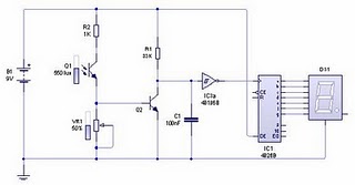
Picture series of infrared sensors | infrared sensor circuit scheme
Component List:
1. Resistors: R1 (33K), R2 (1K), VR1 (Potensio 100K)
2. Capacitors: C1 (100nF)
3. Transistors: Q2 (BC547 should)
4. Photo transistor: Q1
5. IC: 40 106 (Schimitt trigger), 4026 (Decade counter)
6. 7-Segment
WORKING PRINCIPLE:
In the transmitter circuit arrangement so that our task is only an infrared LED lights up and no shortage or excess of power, therefore, use 680 ohm resistors. On The set of photo transistor receiver serves as a useful tool sensor sensed a change in the intensity of infrared light. When infrared light is not on the photo transistor, the photo transistor is like a switch is open so that the transistor is in cutoff position (open). Because the collector and emitter open it in accordance with the laws of the voltage divider, the collector emitter voltage equal to supply voltage (logic high). The output of these collectors would make a series of counter counting irregularly if we did not dampen the bounce output to the input couinter. To reduce the bounce and clarify the logic signal to be our input to counter circuit, we use Schmitt trigger ignition. Schmitt trigger ignition is very useful for those of you who relate to digital circuits, eg, using the damping bounce of mechanical switches on the input digital circuit.
The series of counters that I use here is to use IC 4026 (Decade Counter), one of the family ic CMOS. IC counter counts up if this will get the clock input changes from logic low to high. This IC can directly connect it to the seven segment because the output is designed for seven segment mmang. So you do not need to use as a modifier decoder IC binary value into a score of 7-segment.
To menmgatur you can rotate the sensor sensitivity potensio VR1 at a critical point, or if necessary you can replace R2 with a more appropriate value.Saturday, October 26, 2013
Pressure sensor MPX4100
The pressure sensor (MPX4100) MPX4100 is a pressure sensor that is equipped with signal conditioning circuit and temperature calibrator makes this sensor stable against temperature changes. For this sensor measurement accuracy using micro-machine techniques, thin film metalization and bipolar semiconductor process.

With the signal conditioning circuit, this sensor can connect direct on Analogue to Digital Converter. Signal conditioning circuit generate analog voltage with Full Scale (Full Scale) to 5 Volt. This sensor has the ability to detect the pressure of 15 to 115 kilo Pascal and work under pressure difference between P1 and P2. P1 or Pressure Side consists of gel fluorisilicone that protect it from the objects hard. Pressure sensors on robotic applications are often used as feedback mechanic in which the system microcontroller can detect mechanical condition at the time it. For example to detect strong or weak grip of the robot calculates burden placed on the robot.
Tuesday, October 15, 2013
Alcohol Gas Sensor MQ 3
Alcohol Gas Sensor MQ-3 is an alcohol sensor is suitable for detecting levels of alcohol directly, for example on our breath.
Alcohol Sensor MQ-3 has high sensitivity and fast response time. Alcohol Sensor MQ-3 series drivers for alcohol Sensor MQ-3 is very simple, only need 1 piece of variable resistors. Output of Sensor MQ-3 alcohol in the form of an analog voltage that is proportional to the alcohol content is received. The necessary interface is quite simple, can use the ADC that can respond to voltage 0 volt - 3.3 volt saja.Nilai mounted resistors must be differentiated for various types of gas concentration. So need to be calibrated to 0.4 mg / L (about 200ppm) concentrations of alcohol in the air and on the output resistance of about 200K (100K to 470K) |
| Alcohol Gas Sensor MQ-3 |
Featured Alcohol Gas Sensor MQ-3:
- Sensitivity to high alcohol and low on gasoline
- Fast response and high sensitivity
- Stable and durable
- 5VDC or AC voltage source
- Operating Temperature -10 70 degree C samapai
- Current consumption less than 750mW
Saturday, September 28, 2013
Heat Sensor Fire Detector Pyroelectric

These sensors form of Lithium Tantalate pyroelectric parallel opposed dual element high gain detector with integrated analog signal processing. These sensors can detect heat changes from -40 to +70 degrees Celsius without change siginfikan of noise and sensitivity.
To use heat sensor pyroelectric detectors Eltec E442-3, it can take a kind of cone is covered with a fresnel lens to focus the direction of the infrared ray IR. Heat sensors then pyroelectric detectors Eltec E442-3 inserted into the cone is then connected to the microcontroller. Analog output value signals which when detects heat, the sensor will cause a drastic change in output voltage.
Subscribe to:
Posts (Atom)