Showing posts with label detector. Show all posts
Showing posts with label detector. Show all posts
Thursday, January 9, 2014
SD2 Smoke Detector
This smoke detector circuit diagram is based on the SD2 CMOS Photo-Electric Smoke Detector Integrated Circuit manufactured by Supertex INC and include almost all needed components to build a very simple and high efficiency smoke detector project .As you can see , this smoke detector circuit diagram is very simple an require few external components .
SD2 Smoke Detector Circuit diagram

 The LED predriver output pulses an external transistor which in turn, switches on the infrared light emitting diode at a very low duty cycle. The desired IR LED pulse period is determined by the value of the externai timing resistor. The Smoke Sensitivity is adjustable through a trimmer resistor which varies the IR LED puise width. The light sensing element is a silicon photovoltaic cell which is held at near zero bias to minimize leakage currents. The circuit can detect signals as low as 1 mV and generate an alarm. The IR LED pulse repetition rate increases when smoke is detected. The IR diode can be RCA Type SG 1010A or Spectronics Type SE 5455-4 Clairex and the IR Photo detector can be Vactec VTS4085 .
Because the SD2 CMOS Photo-Electric Smoke Detector IC is designed for use in low power, battery operated, consumer applications it needs a 9 volts DC power supply (or a 9 volts battery ).
SD2 Smoke Detector Circuit diagram
Because the SD2 CMOS Photo-Electric Smoke Detector IC is designed for use in low power, battery operated, consumer applications it needs a 9 volts DC power supply (or a 9 volts battery ).

Sunday, December 15, 2013
Heat Detector Alarm Using the UM3561
A very simple heat detector alarm electronic project can be designed using the UM3561 sound generator circuit and some other common electronic parts . This heat detector electronic circuit project uses a complementary pair comprising npn and pnp transistor to detect heat . Collector of T1 transistor is connected to the base of the T2 transistor , while the collector of T2 transistor is connected to RL1 relay . T3 and T4 transistors connected in darlington configuration are used to amplify the audio signal from the UM3561 ic .
Heat Detector Alarm Circuit diagram

When the temperature close to the T1 transistor is hot , the resistance to the emitter –collector goes low and it starts conducting . In same time T2 transistor conducts , because its base is connected to the collector of T1 transistor and the RL1 relay energized and switches on the siren which produce a fire engine alarm sound . This electronic circuit project must be powered from a 6 volts DC power supply , but the UM3561 IC is powered using a 3 volt zener diode , because the alarm sound require a 3 volts dc power supply . The relay used in this project must be a 6 volt / 100 ohms relay and the speaker must have a 8 ohms load and 1 watt power .
Heat Detector Alarm Circuit diagram
Saturday, November 16, 2013
RF AF signal detector

The series that we will make this is a special electronic circuit can be used to detect the presence or absence of signal AF / RF. The circuit is very neat and simple to make. Costs it takes quite cheap. If you are already assembling this circuit, then with easy reader determine whether there is AF or RF signal at a particular section of a circuit.
Basic circuit uses an audio amplifier and a loudspeaker with switch input for AF and RF signals. The whole device can be made small as possible so it can be included in a container to maintain security. Audio amplifier section in this series created by IC TDA 2822M, with low stereo power amplifier in 8-pin mini-DIP. IC is used as a bridge cofiguration to shrink to 250 mW output power, loudspeaker handle 4 ohm, 500mW. The current required is less than 10mA with voltage of 3V battery.
 |
| RF-AF signal detector schematics |
How it Works circuit
When the selector switch in the AF position, working on the input audio signal AF amplifier input (pin 7 of IC 1) through a capacitor C2 and potentiometer VR1. Capacitors C2 always hold input amplifier of the DC voltage and make it happen in the audio signal frequency. Input Signal IC 1 can be arranged with the help of potentiometers VR1.
When the selector switch in position RF and demodulator detector circuit formed by capacitor C1, diode D1, and resistors R1 and R2 are connected to the input The set. When the audio signal is detected then it will actually go kerangkaian to be strengthened. Signal detection is done by plugging probe (probe) on the legs of the existing components.
Monday, October 28, 2013
AC Line Current Detector
This circuit will detect AC line currents of about 250 mA or more without making any electrical connections to the line. Current is detected by passing one of the AC lines through an inductive pickup (L1) made with a 1 inch diameter U-bolt wound with 800 turns of #30 - #35 magnet wire. The pickup could be made from other iron type rings or transformer cores that allows enough space to pass one of the AC lines through the center. Only one of the current carrying lines, either the line or the neutral should be put through the center of the pickup to avoid the fields cancelling. I tested the circuit using a 2 wire extension cord which I had separated the twin wires a small distance with an exacto knife to allow the U-bolt to encircle only one wire.

The magnetic pickup (U-bolt) produces about 4 millivolts peak for a AC line current of 250 mA, or AC load of around 30 watts. The signal from the pickup is raised about 200 times at the output of the op-amp pin 1 which is then peak detected by the capacitor and diode connected to pin 1. The second op-amp is used as a comparator which detects a voltage rise greater than the diode drop. The minimum signal needed to cause the comparator stage output to switch positive is around 800 mV peak which corresponds to about a 30 watt load on the AC line. The output 1458 op-amp will only swing within a couple volts of ground so a voltage divider (1K/470) is used to reduce the no-signal voltage to about 0.7 volts. An additional diode is added in series with the transistor base to ensure it turns off when the op-amp voltage is 2 volts. You may get a little bit of relay chatter if the AC load is close to the switching point so a larger load of 50 watts or more is recommended. The sensitivity could be increased by adding more turns to the pickup.
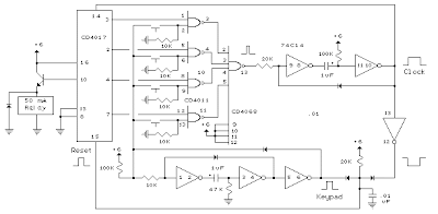
The digital lock shown below uses 4 common logic ICs to allow controlling a relay by entering a 4 digit number on a keypad. The first 4 outputs from the CD4017 decade counter (pins 3,2,4,7) are gated together with 4 digits from a keypad so that as the keys are depressed in the correct order, the counter will advance. As each correct key is pressed, a low level appears at the output of the dual NAND gate producing a high level at the output of the 8 input NAND at pin 13. The momentary high level from pin 13 activates a one shot circuit which applies an approximate 80 millisecond positive going pulse to the clock line (pin 14) of the decade counter which advances it one count on the rising edge. A second monostable, one shot circuit is used to generate an approximate 40 millisecond positive going pulse which is applied to the common point of the keypad so that the appropriate NAND gate will see two logic high levels when the correct key is pressed (one from the counter and the other from the key). The inverted clock pulse (negative going) at pin 12 of the 74C14 and the positive going keypad pulse at pin 6 are gated together using two diodes as an AND gate (shown in lower right corner). The output at the junction of the diodes will be positive in the event a wrong key is pressed and will reset the counter. When a correct key is pressed, outputs will be present from both monostable circuits (clock and keypad) causing the reset line to remain low and allowing the counter to advance. However, since the keypad pulse begins slightly before the clock, a 0.1uF capacitor is connected to the reset line to delay the reset until the inverted clock arrives. The values are not critical and various other timing schemes could be used but the clock signal should be slightly longer than the keypad pulse so that the clock signal can mask out the keypad and avoid resetting the counter in the event the clock pulse ends before the keypad pulse. The fifth output of the counter is on pin 10, so that after four correct key entries have been made, pin 10 will move to a high level and can be used to activate a relay, illuminate an LED, ect. At this point, the lock can be reset simply by pressing any key. The circuit can be extended with additional gates (one more CD4011) to accept up to a 8 digit code. The 4017 counting order is 3 2 4 7 10 1 5 6 9 11 so that the first 8 outputs are connected to the NAND gates and pin 9 would be used to drive the relay or light. The 4 additional NAND gate outputs would connect to the 4 remaining inputs of the CD4068 (pins 9,10,11,12). The circuit will operate from 3 to 12 volts on 4000 series CMOS but only 6 volts or less if 74HC parts are used. The circuit draws very little current (about 165 microamps) so it could be powered for several months on 4 AA batteries assuming only intermittent use of the relay.
Tuesday, October 1, 2013
Metal Detector Based on the TDA0161
These metal detector circuit diagram is based on the TDA0161 monolithic integrated circuit , designed for metallic body detection by detecting the variations in high frequency Eddy current losses. For detecting metals , TDA0161 require an external LC tuned circuit .
Metal Detector Circuit diagram

Output signal is determined by supply current changes. Independent of supply voltage, this current is high or low according to the presence or the absence of a close metallic object. This metal detector circuit use two LEDs , which offer an visual indication of presence or absence at a metals ,around the coil . To adjust the circuit you need to make sure there is no metal near the coil and then set the fine adjustment to a "Mid position". After that you need to adjust the course adjustment to turn on the LED and , adjust the fine adjustment to turn off the LED.
This detector electronic circuit operates over a wide range input voltage of 4 -35 volts . If you want you can use other values for the Cx capacitor and for L1 inductor ( changing this value will affect the frequency oscillation and the detection range ) .
Metal Detector Circuit diagram
This detector electronic circuit operates over a wide range input voltage of 4 -35 volts . If you want you can use other values for the Cx capacitor and for L1 inductor ( changing this value will affect the frequency oscillation and the detection range ) .
Saturday, September 28, 2013
Heat Sensor Fire Detector Pyroelectric
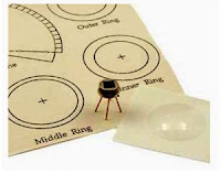
These sensors form of Lithium Tantalate pyroelectric parallel opposed dual element high gain detector with integrated analog signal processing. These sensors can detect heat changes from -40 to +70 degrees Celsius without change siginfikan of noise and sensitivity.
To use heat sensor pyroelectric detectors Eltec E442-3, it can take a kind of cone is covered with a fresnel lens to focus the direction of the infrared ray IR. Heat sensors then pyroelectric detectors Eltec E442-3 inserted into the cone is then connected to the microcontroller. Analog output value signals which when detects heat, the sensor will cause a drastic change in output voltage.
Sunday, September 22, 2013
Metal Detector Schematic Circuit Diagram
 Metal Detector Schematic Circuit Diagram
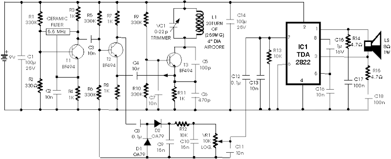
The ambit declared actuality is that of a metal detector. The opera- tion of the ambit is based on superheterodyning assumption which is frequently acclimated in superhet receivers. The ambit utilises two RF oscillators. The frequencies of both oscillators are anchored at 5.5 MHz. The aboriginal RF oscillator comprises transistor T1 (BF 494) and a 5.5MHz bowl clarify frequently acclimated in TV sound-IF section. The additional oscillator is a Colpitt�s oscillator realised with the advice of transistor T3 (BF494) and inductor L1 (whose architecture capacity follow) shunted by trimmer capacitor VC1. These two oscillators� frequencies (say Fx and Fy) are alloyed in the mixer transistor T2 (another BF 494) and the aberration or the exhausted abundance (Fx-Fy) achievement from beneficiary of transistor T2 is affiliated to detector date absolute diodes D1 and D2 (both OA 79).
The achievement is a pulsating DC which is anesthetized through a low-pass clarify realised with the advice of a 10k resistor R12 and two 15nF capacitors C6 and C10. It is again anesthetized to AF amplifier IC1 (2822M) via aggregate ascendancy VR1 and the achievement is fed to an 8-ohm/1W speaker. The inductor L1 can be complete application 15 turns of 25SWG wire on a 10cm (4-inch) bore air-core above and again cementing it with careful varnish. For able operation of the ambit it is analytical that frequencies of both the oscillators are the aforementioned so as to access aught exhausted in the absence of any metal in the abreast around of the circuit.
The alignment of oscillator 2 (to bout oscillator 1 frequency) can be done with the advice of trimmer capacitor VC1. When the two frequencies are equal, the exhausted abundance is zero, i.e. exhausted frquency=Fx-Fy=0, and appropriately there is no complete from the loudspeaker. When chase braid L1 passes over metal, the metal changes its inductance, thereby alteration the additional oscillator�s frequency. So now Fx-Fy is not aught and the loudspeaker sounds. Appropriately one is able to ascertain attendance of metal
The achievement is a pulsating DC which is anesthetized through a low-pass clarify realised with the advice of a 10k resistor R12 and two 15nF capacitors C6 and C10. It is again anesthetized to AF amplifier IC1 (2822M) via aggregate ascendancy VR1 and the achievement is fed to an 8-ohm/1W speaker. The inductor L1 can be complete application 15 turns of 25SWG wire on a 10cm (4-inch) bore air-core above and again cementing it with careful varnish. For able operation of the ambit it is analytical that frequencies of both the oscillators are the aforementioned so as to access aught exhausted in the absence of any metal in the abreast around of the circuit.
The alignment of oscillator 2 (to bout oscillator 1 frequency) can be done with the advice of trimmer capacitor VC1. When the two frequencies are equal, the exhausted abundance is zero, i.e. exhausted frquency=Fx-Fy=0, and appropriately there is no complete from the loudspeaker. When chase braid L1 passes over metal, the metal changes its inductance, thereby alteration the additional oscillator�s frequency. So now Fx-Fy is not aught and the loudspeaker sounds. Appropriately one is able to ascertain attendance of metal
Subscribe to:
Posts (Atom)