Showing posts with label line. Show all posts
Showing posts with label line. Show all posts
Monday, October 28, 2013
AC Line Current Detector
This circuit will detect AC line currents of about 250 mA or more without making any electrical connections to the line. Current is detected by passing one of the AC lines through an inductive pickup (L1) made with a 1 inch diameter U-bolt wound with 800 turns of #30 - #35 magnet wire. The pickup could be made from other iron type rings or transformer cores that allows enough space to pass one of the AC lines through the center. Only one of the current carrying lines, either the line or the neutral should be put through the center of the pickup to avoid the fields cancelling. I tested the circuit using a 2 wire extension cord which I had separated the twin wires a small distance with an exacto knife to allow the U-bolt to encircle only one wire.

The magnetic pickup (U-bolt) produces about 4 millivolts peak for a AC line current of 250 mA, or AC load of around 30 watts. The signal from the pickup is raised about 200 times at the output of the op-amp pin 1 which is then peak detected by the capacitor and diode connected to pin 1. The second op-amp is used as a comparator which detects a voltage rise greater than the diode drop. The minimum signal needed to cause the comparator stage output to switch positive is around 800 mV peak which corresponds to about a 30 watt load on the AC line. The output 1458 op-amp will only swing within a couple volts of ground so a voltage divider (1K/470) is used to reduce the no-signal voltage to about 0.7 volts. An additional diode is added in series with the transistor base to ensure it turns off when the op-amp voltage is 2 volts. You may get a little bit of relay chatter if the AC load is close to the switching point so a larger load of 50 watts or more is recommended. The sensitivity could be increased by adding more turns to the pickup.
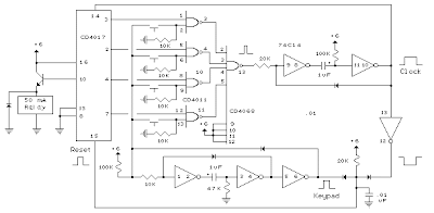
The digital lock shown below uses 4 common logic ICs to allow controlling a relay by entering a 4 digit number on a keypad. The first 4 outputs from the CD4017 decade counter (pins 3,2,4,7) are gated together with 4 digits from a keypad so that as the keys are depressed in the correct order, the counter will advance. As each correct key is pressed, a low level appears at the output of the dual NAND gate producing a high level at the output of the 8 input NAND at pin 13. The momentary high level from pin 13 activates a one shot circuit which applies an approximate 80 millisecond positive going pulse to the clock line (pin 14) of the decade counter which advances it one count on the rising edge. A second monostable, one shot circuit is used to generate an approximate 40 millisecond positive going pulse which is applied to the common point of the keypad so that the appropriate NAND gate will see two logic high levels when the correct key is pressed (one from the counter and the other from the key). The inverted clock pulse (negative going) at pin 12 of the 74C14 and the positive going keypad pulse at pin 6 are gated together using two diodes as an AND gate (shown in lower right corner). The output at the junction of the diodes will be positive in the event a wrong key is pressed and will reset the counter. When a correct key is pressed, outputs will be present from both monostable circuits (clock and keypad) causing the reset line to remain low and allowing the counter to advance. However, since the keypad pulse begins slightly before the clock, a 0.1uF capacitor is connected to the reset line to delay the reset until the inverted clock arrives. The values are not critical and various other timing schemes could be used but the clock signal should be slightly longer than the keypad pulse so that the clock signal can mask out the keypad and avoid resetting the counter in the event the clock pulse ends before the keypad pulse. The fifth output of the counter is on pin 10, so that after four correct key entries have been made, pin 10 will move to a high level and can be used to activate a relay, illuminate an LED, ect. At this point, the lock can be reset simply by pressing any key. The circuit can be extended with additional gates (one more CD4011) to accept up to a 8 digit code. The 4017 counting order is 3 2 4 7 10 1 5 6 9 11 so that the first 8 outputs are connected to the NAND gates and pin 9 would be used to drive the relay or light. The 4 additional NAND gate outputs would connect to the 4 remaining inputs of the CD4068 (pins 9,10,11,12). The circuit will operate from 3 to 12 volts on 4000 series CMOS but only 6 volts or less if 74HC parts are used. The circuit draws very little current (about 165 microamps) so it could be powered for several months on 4 AA batteries assuming only intermittent use of the relay.

Tuesday, October 8, 2013
Driver On Line Follower Robot
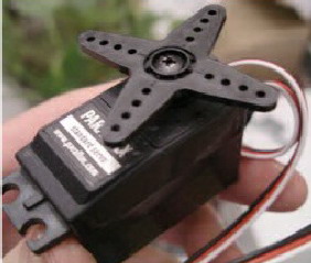
Motor Drive On Line Follower Robot - To move the Line Follower 2 options can be used, namely motor or DC motor servo motor. If you want to use a DC motor, it must use a DC motor is mounted gear system (geared motors DC).Kind of like it is still difficult to find in the market, so the choice often falls to the servo motor.Another advantage of the servo motor is a servo motor can be controlled directly from the microcontroller PIC16F84 with no extra-Driver IC again.
 |
| Motor Drive On Line Follower Robot |
Wheel Drive On Line Follower Robot - Wheels are used in line follower may vary - kinds, ranging from the brand, type, dimensions, and so forth. Line Follower Robot are generally categorized based on the number of wheels it has.Starting from the robot with two wheels, three wheels or four wheels. But that is commonly used is a robot with three or four wheels.
 |
| Wheel Drive On Line Follower Robot |
Placed behind a pair of wheels connected by two motors each - each have an independent pace.It is important that the robot can turn left and to right and set the desired rotation rounds. While the front wheels could use a caster wheel that serves as a buffer. Many brands of caster wheels that can be used, one of the most famous is from the manufacturer Tamiya. However, no cane akarpun so - if we want a cheaper and sometimes free, odor-preventing former rodadeodorant can used as a caster wheel.
In the Line Follower Robot Microcontroller Many types of microcontrollers that can be used in line follower robot, some examples include AT89C2051 (8051 Core), AT89C51 (8051 Core), ATmega8 (AVR Core), ATmega16 (AVR Core) and many more.
In the microcontroller, the program will be included so that the robot can adjust the rotation speed of each motor and able to perform the desired movement. Because the line follower robot speed is high enough, then some of the control algorithm needs to be applied to a robot capable of running smoothly. Control that can be a continuous control, PID, fuzzy logic, or the other.
Speed setting is important, especially when faced with change of trajectory, from a straight trajectory to bend or otherwise of the bend to the straight path. Just as when the robot moves fast and then find a corner, then the robot would be bounced. That requires a series of dynamic motor speed control depending on the type of trajectory is traversed. If the robot goes straight, the speed of the robot cultivated at a maximum. If the condition of the bend, then the speed is reduced depends on the sharpness of the bend. In essence, the speed of the robot is made flexible according to the situation on the ground. On the robot, the speed reduction can be done using the PWM (Pulse widht Modulation) controller, namely the reduction of speed by reducing the current to the motor.
Thursday, September 19, 2013
Creating a Line Follower Robot with AVR
The article "Creating a Line Follower Robot with AVR [Censorship]" is a continuation of Line Follower Robot article with a new AVR ATMega8535 samapai phase Line Follower Robot block diagram. In the article "Creating a Line Follower Robot with AVR Part 1 [Sensor]" This is a review of the sensor used on Line Follower Robot, and the components used. Sensors, can be analogous to the eye of a robot that serves to read the black line of the track robot or vice versa. So that the robot is able to know when he will turn right, when he turned left and when he stopped. Sensors used are usually photo reflector, LDR (Light Dependent Resistor), Photo Diodes and Photo Transistor - mounted on the front two or more below the line follower robot.There also are using the camera as a sensor (or image sensor) to a higher-resolution readout line, making more accurate robot motion.
Line Follower Robot Sensor circuit with AVR ATMega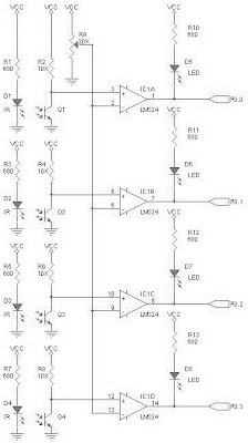 |
| Robot Sensor circuit with AVR ATMega Circuit |
The working principle of the sensor is simple, when the transmitter (infrared) emitting light onto a white field, the light will be reflected back to the receiver by the white areas and vice versa. This gives the change in the voltage level at the receiver output, but it usually changes the voltage can not be accepted as a TTL logic level. To be able to read by the microcontroller, the sensor voltage should be adjusted to TTL voltage level that is 0-1 volts for logic 0 and 3-5 volts for logic 1. This can be done by installing the operational amplifier is used as a comparator as shown in the picture above.
Op Amp is used as a comparator LM324 IC, because IC is able to work at VCC 5 volt range and there are 4 in 1 Op Amp IC corresponding to the number of sensors are used. The sensitivity of this sensor can be set through R9 which controls the comparator reference point.
Maximizing Sensor Line Follower Robot
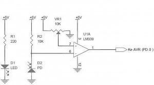
Line follower robot sensors can be made with a combination between LED and photo diode. Line follower robot sensor configuration is good to be able to read the track with a hard and fast. To make the robot sensor is firm and fast can not merely rely on the ability of photo diodes and LED configurations only. As an alternative to maximize the performance of line follower robot sensors can be added to the voltage comparator with Op-Amp. Sensor circuit line follower robot equipped with a voltage comparator that is ready to be connected to a microcontroller or PIC can use the following series of robot sensor.
Line Follower Robot Sensor circuit with voltage comparator
 |
| Voltage comparator Circuit |
Function of the voltage comparator circuit line follower robot sensor above is:
- Reinforce the logic level sensor output
- Amplifies the sensor output signal
- Control and determine the reference point sensor
- Reinforce the logic level sensor output is intended to avoid the floating logic conditions, with the goal of getting the process of transition logic (high) to a logic low (low) or vice versa in a fast sensors. So as to enhance the response to the sensor readings track work.
Sensor output voltage levels should be read as well by the TTL logic processor. If the robot sensors rely on photo diodes and LED configurations, then during the reading process is fast track, then the resulting signal has a logic low loevel differences and can not be read as a TTL logic. Therefore, robot sensor voltage levels are still weak need to be corroborated by a voltage comparator, so the TTL logic level differences firm with a strong signal.
The purpose of controlling and determining the sensor reference point is, we can determine the position of the robot sensor readings can be considered as a logic high or logic low. Choosing process reference value line follower robot sensor readings can be done by adjusting VR1 10kOhm the series "Line Follower Robot Sensor Voltage Comparator With" above.
Subscribe to:
Posts (Atom)