Showing posts with label driver. Show all posts
Showing posts with label driver. Show all posts
Sunday, November 3, 2013
16 Channel LED Driver Using LT3754
The LT3754 16 channel LED driver with a step-up DC DC controller designed by Linear Technology is capable of driving up to 45V of LEDs. Each channel of the LT3754 led driver contains an accurate current sink with ±2.8% current matching.If are used high current Leds channels can be paralleled.
16 Channel LED Driver Circuit Diagram
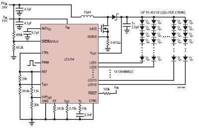
16 Channel LED Driver Circuit Diagram
The LT3754 16 channel LED driver circuit allows a PWM dimming range up to 3000:1 and an analog dimming range up to 25:1. Operating frequency of the LT3574 16 channel LED driver can be programmed from 100kHz up to 1MHz using just a simple resistor or an external clock .

DC motor driver with H Bridge IC L293D
Making a DC motor driver with H-Bridge technique can use IC L293D as in the article "DC Motor Driver H-Bridge L293 (2 Motor DC)"is. DC motor driver L293D can be used to control the DC motor 2 pieces at once. DC Motor Driver L293D can be used to control a DC motor continuously or with a PWM technique. Dc motor driver circuit in the article "DC Motor Driver H-Bridge L293 (2 Motor DC)" only use IC L293D only. For more details see the following figure.
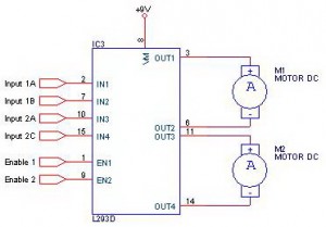
Working system of DC motor driver L293D is to provide control signals in the form of logic or pulse to the input lines 1A - 1B for DC motor control M1 and the input 2A - 2B for the control of DC motor M2 with the following conditions:
Input A Input B Motor DC0 0 Motor silent
1 0 motor rotates counterclockwise
0 1 Motor berputer clockwise
1 1 Motor silent
Description: Enable Input given a logic 1 to obtain such data in the table above.
Thursday, October 24, 2013
Simple Operational Amplifier DC Motor Driver
Using a simple operational amplifier and some other common electronic components can be designed a very simple DC motor driver that can be used for a 200mA motor application . Rb sets the bias point for transistors Q1 and Q2.

Because Vbe(ON) varies greatly with temperature, a guardband is required to prevent Q1 and Q2 from conducting simultaneously. RB should be selected such that the transistors do not conduct until lM equals the op amp quiescent supply current, Isy . The transistors will begin to conduct at about Vbe (on) = 0.5V. In this project :
RB= [vbe(on)/(lSY+ Im)]= 0.5/(0.0025 + 0.0025)=100 ohms
To maximize voltage swing across the motor, V1 must be minimized. If at full load V1 = 0.2V with V+ = 15V and VBE1 = 0.8V, the voltage across the motor will be:
VM = (V+ - 2) - VBE1 - V1 = (15 - 2) - 0.8 - 0.2 = 12.0V Vin may be scaled with a resistive divider as:
VIN= (R1 + R2)/R2 With R1 = 240k and R2 = 10k, VIN =5 volt lM = 200mA.
RB= [vbe(on)/(lSY+ Im)]= 0.5/(0.0025 + 0.0025)=100 ohms
To maximize voltage swing across the motor, V1 must be minimized. If at full load V1 = 0.2V with V+ = 15V and VBE1 = 0.8V, the voltage across the motor will be:
VM = (V+ - 2) - VBE1 - V1 = (15 - 2) - 0.8 - 0.2 = 12.0V Vin may be scaled with a resistive divider as:
VIN= (R1 + R2)/R2 With R1 = 240k and R2 = 10k, VIN =5 volt lM = 200mA.
Monday, October 21, 2013
Charge Pump LED Driver Using CAT3649
A very simple LED driver electronic project can be designed using the CAT3649 high efficiency quad mode R fractional charge pump IC that can drive up to six LEDs. The inclusion of a 1.33x fractional charge pump mode increases the device efficiency by up to 10% over traditional 1.5x charge pumps with no added external capacitors.Low noise input ripple is achieved by operating at a constant switching frequency which allows the use of small external ceramic capacitors. The multi−fractional charge pump supports a wide range of input voltages from 2.4 V to 5.5 V.

The LED current can be adjusted in different ways. The full−scale LED current is set to 25 mA once the device is enabled. Analog dimming in 32 linear steps is achieved via a 1−wire pulse−dimming input (ADIM)
Further adjustment of the LED current can be done by applying a pulse width modulation (PWM) signal on the PWM input.The CAT3649 can be shut down by holding the ADIM or PWM input in a logic low condition for greater than 30 ms. This electronic design CAT3649 charge pump LED driver can be used in applications like : LCD Display Backlight , Cellular Phones , Digital Still Cameras and some other handheld devices .
If the input voltage is insufficient or falls to a level where the regulated currents cannot be maintained, the CAT3649 automatically switches into 1.33x mode. In 1.33x mode, the output voltage is approximately equal to 1.33 times the input supply voltage . This sequence repeats in the 1.33x and 1.5x mode until the driver enters the 2x mode.While in 2x mode, the output is approximately equal to 2 times the input supply voltage.If the CAT3649 charge pump LED driver detects a sufficient input voltage to drive all LED currents in 1x mode, it will change automatically back to 1x mode.
The LED current can be adjusted in different ways. The full−scale LED current is set to 25 mA once the device is enabled. Analog dimming in 32 linear steps is achieved via a 1−wire pulse−dimming input (ADIM)
Further adjustment of the LED current can be done by applying a pulse width modulation (PWM) signal on the PWM input.The CAT3649 can be shut down by holding the ADIM or PWM input in a logic low condition for greater than 30 ms. This electronic design CAT3649 charge pump LED driver can be used in applications like : LCD Display Backlight , Cellular Phones , Digital Still Cameras and some other handheld devices .
If the input voltage is insufficient or falls to a level where the regulated currents cannot be maintained, the CAT3649 automatically switches into 1.33x mode. In 1.33x mode, the output voltage is approximately equal to 1.33 times the input supply voltage . This sequence repeats in the 1.33x and 1.5x mode until the driver enters the 2x mode.While in 2x mode, the output is approximately equal to 2 times the input supply voltage.If the CAT3649 charge pump LED driver detects a sufficient input voltage to drive all LED currents in 1x mode, it will change automatically back to 1x mode.
Saturday, October 19, 2013
PBL3717A Motor Stepper Driver
This motor stepper driver electronic project is designed using the PBL3717 motor driver manufactured by ST Microelectronics . The PBL3717A motor stepper driveris a monolithic IC which controls and drives one phase of a bipolar stepper motor with chopper control of the phase current. Current levels may be selected in three steps by means of two logic inputs which select one of three current comparators.
PBL3717A Motor Stepper Driver Circuit Diagram

When both of these inputs are high the device is disabled. A separate logic input controls the direction of current flow. A monostable, programmed by an external RC network, sets the current decay time. The output current for this project is up to 1A from 10 up to 46 volt motor supply . The logic inputs I0 and I1 set at three different levels the amplitude of the current flowing in the motor winding .
A high level on the "PHASE" logic input sets the direction of that current from output A to output B and a low level from output B to output A. It is recommended that unused inputs are tied to pin 6 (Vss) or pin 4 (GND) as appropriate to avoid noise problem. The current levels can be varied continuously by changing the reference voltage on pin 11. In this bipolar stepper motor driver project , the Vss is the logic power and must be around 5 volt and VS is the motor power and must be between 10 and 46 volts .
PBL3717A Motor Stepper Driver Circuit Diagram
When both of these inputs are high the device is disabled. A separate logic input controls the direction of current flow. A monostable, programmed by an external RC network, sets the current decay time. The output current for this project is up to 1A from 10 up to 46 volt motor supply . The logic inputs I0 and I1 set at three different levels the amplitude of the current flowing in the motor winding .
A high level on the "PHASE" logic input sets the direction of that current from output A to output B and a low level from output B to output A. It is recommended that unused inputs are tied to pin 6 (Vss) or pin 4 (GND) as appropriate to avoid noise problem. The current levels can be varied continuously by changing the reference voltage on pin 11. In this bipolar stepper motor driver project , the Vss is the logic power and must be around 5 volt and VS is the motor power and must be between 10 and 46 volts .
Sunday, October 13, 2013
High Efficiency 12V White LED Driver
DC powered LED lighting circuits can vary from trivial single LED/series resistor combos to simple analog current regulators to more complicated switching power supply circuits such as this project. There is a tradeoff between simplicity and circuit capabilities. This more complex circuit adds features such as regulated light level across a wide range of input voltages and automatic circuit shutoff on low input voltage. By using a high frequency switching regulator, the power loss associated with the current dropping resistors found in simpler circuits is reduced. This offsets the power consumed by the circuits active parts. This circuit can power 10 white LEDs at 24mA of current with only 98mA of input supply current when running on 12V. LED intensity is fully regulated across the entire operating voltage range.
High Efficiency 12V White LED Driver Circuit Diagram
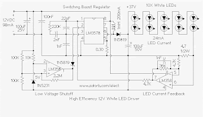
This circuit was inspired by F. Garcias IR LED video illumination circuit, published in the July 2001 edition of Nuts and Volts magazine. I modified the LED count and feedback circuit, and added the important low voltage shutdown feature.
Specifications:
The heart of the circuit is a string of 10 white LEDs. These are wired in series and connected to a current-regulated step-up switching power supply circuit.
The LM3578 switching regulator and its associated inductor, 1N5819 schottky diode, and 100uF 50V capacitor step the 12V power supply up to a higher DC voltage. The voltage is approximately 3.7 X the number of LEDs. The 4.7 ohm resistor on the cathode end of the LED string develops a voltage that is proportional to the current through the LEDs. This voltage is amplified by half of the LM358 op-amp and sends a negative feedback signal through a 4.7K resistor back to the LM3578. The 36K feedback resistor across the LM358 sets the LED series current to approximately 24mA. Not all general purpose op-amps will work in this circuit, the LM358 can operate from a single-rail power supply with both input pins near 0V.
The other half of the LM358 (pins 1,2,3) is wired as a 10V voltage comparator. The 1N5231 zener diode and 10K series resistor produces a steady 5V on pin 2 of the LM358. The two 100K resistors on pin 3 of the LM358 divide the input voltage in half. If the supply voltage drops below 10V, the output of the LM358 drops, and pulls pin 2 of the LM3578 down through a 1N5819 schottky diode, causing the LM3578 to shut down. A schottky diode is used instead of a standard silicon diode in order for the LM3578 pin 2 voltage to go low enough to disable the circuit. Without the low voltage shutdown circuit, the LM3578 current will increase as the supply voltage decreases until the IC self-destructs.
The 2.2M resistor across the LM358 produces a hysteresis effect for the low voltage shutoff. The circuit turns off about .25V below where it turns back on, this prevents oscillation around the shutoff threshold. Below the low voltage shutoff point, the circuit will consume about 5mA of current.
An interesting characteristic of this circuit is that it acts as a negative resistance at the power supply terminals. As the supply voltage is increased, the current will drop. The total power consumption stays nearly even across changing input voltage conditions.
Use:
Just connect the circuit to a 12V DC power supply, such as a solar charged lead acid battery. The light level will remain constant through the battery voltage change, and the circuit will consume a minimal amount of power.
It is possible to vary the number of white LEDs in this circuit from 8 to 12, as the LED count goes up, so does the regulators output voltage and input current. Numerous readers have asked me if this circuit can drive more than 12 3.7V white LEDs, 12 white LEDs is about the maximum upper power limit for the LM3578 IC. If you are driving lower voltage LEDs such as 1.4V IR or red parts, the series string can have up to 30 LEDs.
Parts:
1X LM3578AN switch-mode voltage regulator IC
1X LM358P dual op-amp
1X 1N5231 5V zener diode
2X 1N5819 schottky diodes
10X high intensity white LEDs
1X 100uF 25V electrolytic capacitor
1X 100uF 50V electrolytic capacitor
1X 100nF 50V ceramic or MLCC capacitors
1X 2nF 50V ceramic or MLCC capacitor
2X 1nF 50V ceramic or MLCC capacitors
1X 22pF ceramic disc capacitor
1X 0.3 ohm 1/4 W resistor (Substitutes: 3X 1 ohm or 2X 0.62 ohm 1/4W resistors in parallel)
1X 4.7 ohm 1/2W resistor
2X 4.7K 1/4W resistors
1X 10K 1/4W resistor
1X 36K 1/4W resistor
2X 100K 1/4W resistors
1X 220K 1/4W resistor
1X 2.2M 1/4W resistor
1X 1mH 200mA switching power supply inductor
Inductors that are known to work:
Mouser part 851-CDRH74NP-102MC (Sumida SMD)
Digi-Key part TKS3504CT-ND (Toko 875FU-102M=P3)
High Efficiency 12V White LED Driver Circuit Diagram
This circuit was inspired by F. Garcias IR LED video illumination circuit, published in the July 2001 edition of Nuts and Volts magazine. I modified the LED count and feedback circuit, and added the important low voltage shutdown feature.
Specifications:
- Power Requirements:
- Operating Voltage: 10-18V DC
- Operating Current: 98mA @ 12V DC (10 LEDs)
- Current at low voltage shutoff point: 5mA
The heart of the circuit is a string of 10 white LEDs. These are wired in series and connected to a current-regulated step-up switching power supply circuit.
The LM3578 switching regulator and its associated inductor, 1N5819 schottky diode, and 100uF 50V capacitor step the 12V power supply up to a higher DC voltage. The voltage is approximately 3.7 X the number of LEDs. The 4.7 ohm resistor on the cathode end of the LED string develops a voltage that is proportional to the current through the LEDs. This voltage is amplified by half of the LM358 op-amp and sends a negative feedback signal through a 4.7K resistor back to the LM3578. The 36K feedback resistor across the LM358 sets the LED series current to approximately 24mA. Not all general purpose op-amps will work in this circuit, the LM358 can operate from a single-rail power supply with both input pins near 0V.
The other half of the LM358 (pins 1,2,3) is wired as a 10V voltage comparator. The 1N5231 zener diode and 10K series resistor produces a steady 5V on pin 2 of the LM358. The two 100K resistors on pin 3 of the LM358 divide the input voltage in half. If the supply voltage drops below 10V, the output of the LM358 drops, and pulls pin 2 of the LM3578 down through a 1N5819 schottky diode, causing the LM3578 to shut down. A schottky diode is used instead of a standard silicon diode in order for the LM3578 pin 2 voltage to go low enough to disable the circuit. Without the low voltage shutdown circuit, the LM3578 current will increase as the supply voltage decreases until the IC self-destructs.
The 2.2M resistor across the LM358 produces a hysteresis effect for the low voltage shutoff. The circuit turns off about .25V below where it turns back on, this prevents oscillation around the shutoff threshold. Below the low voltage shutoff point, the circuit will consume about 5mA of current.
An interesting characteristic of this circuit is that it acts as a negative resistance at the power supply terminals. As the supply voltage is increased, the current will drop. The total power consumption stays nearly even across changing input voltage conditions.
Use:
Just connect the circuit to a 12V DC power supply, such as a solar charged lead acid battery. The light level will remain constant through the battery voltage change, and the circuit will consume a minimal amount of power.
It is possible to vary the number of white LEDs in this circuit from 8 to 12, as the LED count goes up, so does the regulators output voltage and input current. Numerous readers have asked me if this circuit can drive more than 12 3.7V white LEDs, 12 white LEDs is about the maximum upper power limit for the LM3578 IC. If you are driving lower voltage LEDs such as 1.4V IR or red parts, the series string can have up to 30 LEDs.
Parts:
1X LM3578AN switch-mode voltage regulator IC
1X LM358P dual op-amp
1X 1N5231 5V zener diode
2X 1N5819 schottky diodes
10X high intensity white LEDs
1X 100uF 25V electrolytic capacitor
1X 100uF 50V electrolytic capacitor
1X 100nF 50V ceramic or MLCC capacitors
1X 2nF 50V ceramic or MLCC capacitor
2X 1nF 50V ceramic or MLCC capacitors
1X 22pF ceramic disc capacitor
1X 0.3 ohm 1/4 W resistor (Substitutes: 3X 1 ohm or 2X 0.62 ohm 1/4W resistors in parallel)
1X 4.7 ohm 1/2W resistor
2X 4.7K 1/4W resistors
1X 10K 1/4W resistor
1X 36K 1/4W resistor
2X 100K 1/4W resistors
1X 220K 1/4W resistor
1X 2.2M 1/4W resistor
1X 1mH 200mA switching power supply inductor
Inductors that are known to work:
Mouser part 851-CDRH74NP-102MC (Sumida SMD)
Digi-Key part TKS3504CT-ND (Toko 875FU-102M=P3)
Tuesday, October 8, 2013
Driver On Line Follower Robot
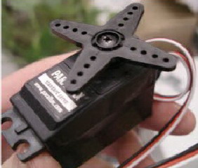
Motor Drive On Line Follower Robot - To move the Line Follower 2 options can be used, namely motor or DC motor servo motor. If you want to use a DC motor, it must use a DC motor is mounted gear system (geared motors DC).Kind of like it is still difficult to find in the market, so the choice often falls to the servo motor.Another advantage of the servo motor is a servo motor can be controlled directly from the microcontroller PIC16F84 with no extra-Driver IC again.
 |
| Motor Drive On Line Follower Robot |
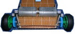
Wheel Drive On Line Follower Robot - Wheels are used in line follower may vary - kinds, ranging from the brand, type, dimensions, and so forth. Line Follower Robot are generally categorized based on the number of wheels it has.Starting from the robot with two wheels, three wheels or four wheels. But that is commonly used is a robot with three or four wheels.
 |
| Wheel Drive On Line Follower Robot |
Placed behind a pair of wheels connected by two motors each - each have an independent pace.It is important that the robot can turn left and to right and set the desired rotation rounds. While the front wheels could use a caster wheel that serves as a buffer. Many brands of caster wheels that can be used, one of the most famous is from the manufacturer Tamiya. However, no cane akarpun so - if we want a cheaper and sometimes free, odor-preventing former rodadeodorant can used as a caster wheel.
In the Line Follower Robot Microcontroller Many types of microcontrollers that can be used in line follower robot, some examples include AT89C2051 (8051 Core), AT89C51 (8051 Core), ATmega8 (AVR Core), ATmega16 (AVR Core) and many more.
In the microcontroller, the program will be included so that the robot can adjust the rotation speed of each motor and able to perform the desired movement. Because the line follower robot speed is high enough, then some of the control algorithm needs to be applied to a robot capable of running smoothly. Control that can be a continuous control, PID, fuzzy logic, or the other.
Speed setting is important, especially when faced with change of trajectory, from a straight trajectory to bend or otherwise of the bend to the straight path. Just as when the robot moves fast and then find a corner, then the robot would be bounced. That requires a series of dynamic motor speed control depending on the type of trajectory is traversed. If the robot goes straight, the speed of the robot cultivated at a maximum. If the condition of the bend, then the speed is reduced depends on the sharpness of the bend. In essence, the speed of the robot is made flexible according to the situation on the ground. On the robot, the speed reduction can be done using the PWM (Pulse widht Modulation) controller, namely the reduction of speed by reducing the current to the motor.
Tuesday, October 1, 2013
LED Driver Design using TCA62735AFLG LED Driver IC
The TCA62735AFLG is a charge pump type DC DC Converter specially designed for constant current driving of white LED.IC can outputs LED current 120mA or more to 2.8-4.2V input.IC observes the power-supply voltage and the output voltage, and does an automatic change to the best of step up mode 1, 1.5 or 2 times. It is possible to prolong the battery longevity to its maximum.This IC is especially for driving back light white LEDs in LCD of PDA, Cellular Phone, or Handy Terminal Equipment.
Schematic

This electronic project t LED driver is very simple and require few external electronic parts. Due of simplicity of this circuit this project not require additional explanations . If you want to change this design , please consult the manufactured datasheet .Some features of the TCA62735AFLG electronic project are Switching Frequency : 1MHz(Typ.), Output Drive Current Capability : Greater than 120mA , 4 Channels Built in Constant Sink Current Drivers, Sink Current Adjustment by External Resistance, Soft Start Function , Integrated protection circuit TSD (Thermal Shut Down) .
Schematic
This electronic project t LED driver is very simple and require few external electronic parts. Due of simplicity of this circuit this project not require additional explanations . If you want to change this design , please consult the manufactured datasheet .Some features of the TCA62735AFLG electronic project are Switching Frequency : 1MHz(Typ.), Output Drive Current Capability : Greater than 120mA , 4 Channels Built in Constant Sink Current Drivers, Sink Current Adjustment by External Resistance, Soft Start Function , Integrated protection circuit TSD (Thermal Shut Down) .
Friday, September 13, 2013
MAX1573 White LED Driver Schematic
This white LED driver electronic project circuit is designed using the MAX1573 integrated circuit , manufactured by Maxim Semiconductor.This white led driver circuit circuit drives as many as four white LEDs in parallel from a 3.3V source, and adjusts the total LED current from 1mA to 106mA, in 64 steps of 1dB each .To control the LED brightness, op amp U2 monitors the difference between the high-side voltage and the wiper voltage of digital potentiometer U1. The op amp then multiplies that voltage by a gain to set the maximum output current.
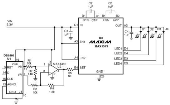
Zero resistance at the pots W1 terminal corresponds to minimum LED current, and therefore minimum brightness. Because the SET voltage is fixed (at 0.6V), any voltage change at the left side of R5 changes ISET, and the resulting change in LED currents changes their brightness level. R5 sets the maximum LED current: R5 = 215x0.6/ILED(Desired) (ILED is the current through one LED) .U1 integrated circuit is a digital potentiometer with logarithmic taper and an analog-voltage wiper for which each tap corresponds to 1dB of attenuation between H1 and W1 (pins 11 and 9).
Zero resistance at the pots W1 terminal corresponds to minimum LED current, and therefore minimum brightness. Because the SET voltage is fixed (at 0.6V), any voltage change at the left side of R5 changes ISET, and the resulting change in LED currents changes their brightness level. R5 sets the maximum LED current: R5 = 215x0.6/ILED(Desired) (ILED is the current through one LED) .U1 integrated circuit is a digital potentiometer with logarithmic taper and an analog-voltage wiper for which each tap corresponds to 1dB of attenuation between H1 and W1 (pins 11 and 9).
Subscribe to:
Posts (Atom)