Showing posts with label motor. Show all posts
Showing posts with label motor. Show all posts
Friday, January 10, 2014
DC Servo Motor Controller
As we presented in another article the A3952S integrated circuit ( designed by Allegro MicroSystems ) can be used to design very simple and useful motor driver circuits . In the precedent article was presented a simple bipolar stepper motor driver circuit that use two A3952S circuits. As we presented in that article , the A3952S is capable of continuous output currents up to 2 A and operating voltages range up to 50 V.
DC Servo Motor Controller Circuit diagram

Warning , the 50 operating voltage is to power the motor , for the logic controller you will need a 5 volts Dc power supply .
This circuit presents a simple DC servo motor application that can be used in various electronic projects . As you can see in the circuit schematic this Dc servo motor driver schematic circuit use just one integrated circuit and other few external electronic components . With bidirectional dc servo motors, the PHASE terminal can be used for mechanical direction control. Similar to when braking the motor dynamically, abrupt changes in the direction of a rotating motor produce a current generated by the back EMF. The current generated will depend on the mode of operation.
DC Servo Motor Controller Circuit diagram
This circuit presents a simple DC servo motor application that can be used in various electronic projects . As you can see in the circuit schematic this Dc servo motor driver schematic circuit use just one integrated circuit and other few external electronic components . With bidirectional dc servo motors, the PHASE terminal can be used for mechanical direction control. Similar to when braking the motor dynamically, abrupt changes in the direction of a rotating motor produce a current generated by the back EMF. The current generated will depend on the mode of operation.
Wednesday, December 25, 2013
L297 Stepper Motor Controller Circuits
 L297 Stepper Motor Controller Circuits
Four appearance drive signals for two appearance bipolar and four appearance unipolar footfall motors in microcomputer-controlled appliance is calmly implemented application L29 Stepper Motor Controller IC. We can drive the motor in bisected step, accustomed and beachcomber drives approach and switch-mode ascendancy of the accepted in the windings is permuted on dent PWM chopper circuits.
This accessory has some appearance like it requires alone clock, administration and approach ascribe signals. Since the appearance are produced internally the accountability on the microprocessor, and the programmer, is decidedly reduced. This accessory is army in DIP20 and SO20 packages. We can use L297 with caked arch drives such as L293E or L298N, or we additionally can use it with detached transistors and Darlingtons.
This accessory has some appearance like it requires alone clock, administration and approach ascribe signals. Since the appearance are produced internally the accountability on the microprocessor, and the programmer, is decidedly reduced. This accessory is army in DIP20 and SO20 packages. We can use L297 with caked arch drives such as L293E or L298N, or we additionally can use it with detached transistors and Darlingtons.
Friday, December 20, 2013
LMD18200 Motor Controller Schematic
Using the LMD18200 3A H-Bridge designed by National Semiconductors for motion control applications can be designed a very simple motor controller electronic project . Ideal for driving DC and stepper motors; the LMD18200 accommodates peak output currents up to 6A. An innovative circuit which facilitates low-loss sensing of the output current has been implemented.
LMD18200 Motor Controller Schematic

This circuit controls the current through the motor by applying an average voltage equal to zero to the motor terminals for a fixed period of time, whenever the current through the motor exceeds the commanded current. This action causes the motor current to vary slightly about an externally controlled average level. The duration of the Off-period is adjusted by the resistor and capacitor combination of the LM555.
Using this motor driver circuit you can design a 24 DC motor that require a maximum current consumption of 3 amperes .
LMD18200 Motor Controller Schematic
Using this motor driver circuit you can design a 24 DC motor that require a maximum current consumption of 3 amperes .
Saturday, November 16, 2013
L6203 DC Motor Controller
This DC motor controller circuit shown in this schematic use the L620x motor driver . The L620x is a monolithic full bridge switching motor driver realized in the new Multipower-BCD technology which allows the integration of multiple, isolated DMOS power transistors plus mixed CMOS/bipolar control circuits and is available in many versions : L6201 /1PS/2/3 .
L6203 DC Motor Controller Schematic

All this motor driver circuits are identically , the differences between them is the total RMS current , which is up to : 1A for L6201 , 2A for L6202 and 4A for L6203 and L6201PS . If the device is combined with a current regulator like the L6506 , can be implemented a transconductance amplifier for speed control, as shown in this circuit schematic . In this configuration only half of the L6506 is used and the other half of the device may be used to control a second motor.
The L6506 senses the voltage across the sense resistor RS to monitor the motor current: it compares the sensed voltage both to control the speed and during the brake of the motor. A snubber network made by the series of R and C must be foreseen very near to the output pins of the I.C.
The following formulas can be used to calculate the snubber values:
R @ VS/lp ; C = lp/(dV/dt) where:
VS is the maximum Supply Voltage foreseen on the application; Ip is the peak of the load current; dv/dt is the limited rise time of the output voltage (200V/ms is generally used).
of the IC. Sometimes a capacitor at pin 17 of the L6506 let the application better work.
L6203 DC Motor Controller Schematic
The L6506 senses the voltage across the sense resistor RS to monitor the motor current: it compares the sensed voltage both to control the speed and during the brake of the motor. A snubber network made by the series of R and C must be foreseen very near to the output pins of the I.C.
The following formulas can be used to calculate the snubber values:
R @ VS/lp ; C = lp/(dV/dt) where:
VS is the maximum Supply Voltage foreseen on the application; Ip is the peak of the load current; dv/dt is the limited rise time of the output voltage (200V/ms is generally used).
of the IC. Sometimes a capacitor at pin 17 of the L6506 let the application better work.
Sunday, November 3, 2013
DC motor driver with H Bridge IC L293D
Making a DC motor driver with H-Bridge technique can use IC L293D as in the article "DC Motor Driver H-Bridge L293 (2 Motor DC)"is. DC motor driver L293D can be used to control the DC motor 2 pieces at once. DC Motor Driver L293D can be used to control a DC motor continuously or with a PWM technique. Dc motor driver circuit in the article "DC Motor Driver H-Bridge L293 (2 Motor DC)" only use IC L293D only. For more details see the following figure.
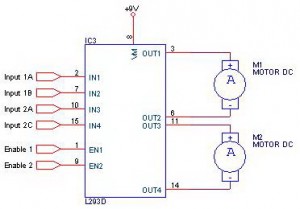
Working system of DC motor driver L293D is to provide control signals in the form of logic or pulse to the input lines 1A - 1B for DC motor control M1 and the input 2A - 2B for the control of DC motor M2 with the following conditions:
Input A Input B Motor DC0 0 Motor silent
1 0 motor rotates counterclockwise
0 1 Motor berputer clockwise
1 1 Motor silent
Description: Enable Input given a logic 1 to obtain such data in the table above.
Thursday, October 24, 2013
Simple Operational Amplifier DC Motor Driver
Using a simple operational amplifier and some other common electronic components can be designed a very simple DC motor driver that can be used for a 200mA motor application . Rb sets the bias point for transistors Q1 and Q2.

Because Vbe(ON) varies greatly with temperature, a guardband is required to prevent Q1 and Q2 from conducting simultaneously. RB should be selected such that the transistors do not conduct until lM equals the op amp quiescent supply current, Isy . The transistors will begin to conduct at about Vbe (on) = 0.5V. In this project :
RB= [vbe(on)/(lSY+ Im)]= 0.5/(0.0025 + 0.0025)=100 ohms
To maximize voltage swing across the motor, V1 must be minimized. If at full load V1 = 0.2V with V+ = 15V and VBE1 = 0.8V, the voltage across the motor will be:
VM = (V+ - 2) - VBE1 - V1 = (15 - 2) - 0.8 - 0.2 = 12.0V Vin may be scaled with a resistive divider as:
VIN= (R1 + R2)/R2 With R1 = 240k and R2 = 10k, VIN =5 volt lM = 200mA.
Saturday, October 19, 2013
PBL3717A Motor Stepper Driver
This motor stepper driver electronic project is designed using the PBL3717 motor driver manufactured by ST Microelectronics . The PBL3717A motor stepper driveris a monolithic IC which controls and drives one phase of a bipolar stepper motor with chopper control of the phase current. Current levels may be selected in three steps by means of two logic inputs which select one of three current comparators.
PBL3717A Motor Stepper Driver Circuit Diagram

When both of these inputs are high the device is disabled. A separate logic input controls the direction of current flow. A monostable, programmed by an external RC network, sets the current decay time. The output current for this project is up to 1A from 10 up to 46 volt motor supply . The logic inputs I0 and I1 set at three different levels the amplitude of the current flowing in the motor winding .
A high level on the "PHASE" logic input sets the direction of that current from output A to output B and a low level from output B to output A. It is recommended that unused inputs are tied to pin 6 (Vss) or pin 4 (GND) as appropriate to avoid noise problem. The current levels can be varied continuously by changing the reference voltage on pin 11. In this bipolar stepper motor driver project , the Vss is the logic power and must be around 5 volt and VS is the motor power and must be between 10 and 46 volts .
PBL3717A Motor Stepper Driver Circuit Diagram
When both of these inputs are high the device is disabled. A separate logic input controls the direction of current flow. A monostable, programmed by an external RC network, sets the current decay time. The output current for this project is up to 1A from 10 up to 46 volt motor supply . The logic inputs I0 and I1 set at three different levels the amplitude of the current flowing in the motor winding .
A high level on the "PHASE" logic input sets the direction of that current from output A to output B and a low level from output B to output A. It is recommended that unused inputs are tied to pin 6 (Vss) or pin 4 (GND) as appropriate to avoid noise problem. The current levels can be varied continuously by changing the reference voltage on pin 11. In this bipolar stepper motor driver project , the Vss is the logic power and must be around 5 volt and VS is the motor power and must be between 10 and 46 volts .
Thursday, October 10, 2013
A3952S Stepper Motor Controller Schematic
Using the A3952S stepper motor controller designed by Allegro MicroSystems can be designed a very simple and useful motor driver circuit that can be used in many electronic applications . A3952S stepper motor controller is capable of continuous output currents up to 2 A and operating voltages range up to 50 V. Internal fixed off-time PWM current-control circuitry can be used to regulate the maximum load current to a desired value.
A3952S Stepper Motor Controller Schematic

The MODE terminal can be used to optimize the performance of the device in microstepping / sinusoidal stepper motor drive applications. When the average load current is increasing, slow-decay mode is used to limit the switching losses in the device and iron losses in the motor.
The thermal performance in applications with high load currents and/or high duty cycles can be improved by adding external diodes in parallel with the internal diodes. In internal PWM slow-decay applications, only the two top-side (flyback) diodes need be added. For internal fast-decay PWM, or external PHASE or ENABLE input PWM applications, all four external diodes should be added for maximum junction temperature reduction .
A3952S Stepper Motor Controller Schematic
The thermal performance in applications with high load currents and/or high duty cycles can be improved by adding external diodes in parallel with the internal diodes. In internal PWM slow-decay applications, only the two top-side (flyback) diodes need be added. For internal fast-decay PWM, or external PHASE or ENABLE input PWM applications, all four external diodes should be added for maximum junction temperature reduction .
Subscribe to:
Posts (Atom)