Showing posts with label simple. Show all posts
Showing posts with label simple. Show all posts
Saturday, October 18, 2014
Simple Temperature Sensor Arduino
Hello people, it’s been a while since I have posted projects on this website. This semester was really busy, I didn’t have time to much else, but soon I will have my winter holiday (Here in south our summer holiday is from December to February).
Today I am going to show you how to build a simple temperature sensor using one LM35 Precision Temperature Sensor and Arduino, so you can hookup on your future projects. The circuit will send serial information about the temperature so you can use on your computer, change the code as you will. I’m planning to build a temperature sensor with max/min + clock + LCD, and when I get it done, I will post here.
Parts:
This is a quick and simple step. Just connect the 5V output from arduino to the 1st pin of the sensor, ground the 3rd pin and the 2nd one, you connect to the 0 Analog Input.
Down goes some pictures that may help you, click to enlarge:


Here is the Arduino Code, just upload it and check the Serial Communication Option.
You can also download the .pde HERE.
Anything just ask!
Source by : link
Today I am going to show you how to build a simple temperature sensor using one LM35 Precision Temperature Sensor and Arduino, so you can hookup on your future projects. The circuit will send serial information about the temperature so you can use on your computer, change the code as you will. I’m planning to build a temperature sensor with max/min + clock + LCD, and when I get it done, I will post here.
Parts:
- Arduino (You can use other microcontroller, but then you will need to change the code).
- LM35 Precision Centigrade Temperature Sensor, you can get from any electronic store. Here is the DATA SHEET.
- BreadBoard
This is a quick and simple step. Just connect the 5V output from arduino to the 1st pin of the sensor, ground the 3rd pin and the 2nd one, you connect to the 0 Analog Input.
Down goes some pictures that may help you, click to enlarge:
Here is the Arduino Code, just upload it and check the Serial Communication Option.
You can also download the .pde HERE.
/*
An open-source LM35DZ Temperature Sensor for Arduino. This project will be enhanced on a regular basis
(cc) by Daniel Spillere Andrade , http://www.danielandrade.net
http://creativecommons.org/license/cc-gpl
*/
int pin = 0; // analog pin
int tempc = 0,tempf=0; // temperature variables
int samples[8]; // variables to make a better precision
int maxi = -100,mini = 100; // to start max/min temperature
int i;
void setup()
{
Serial.begin(9600); // start serial communication
}
void loop()
{
for(i = 0;i< =7;i++){ // gets 8 samples of temperature
samples[i] = ( 5.0 * analogRead(pin) * 100.0) / 1024.0;
tempc = tempc + samples[i];
delay(1000);
}
tempc = tempc/8.0; // better precision
tempf = (tempc * 9)/ 5 + 32; // converts to fahrenheit
if(tempc > maxi) {maxi = tempc;} // set max temperature
if(tempc < mini) {mini = tempc;} // set min temperature
Serial.print(tempc,DEC);
Serial.print(" Celsius, ");
Serial.print(tempf,DEC);
Serial.print(" fahrenheit -> ");
Serial.print(maxi,DEC);
Serial.print(" Max, ");
Serial.print(mini,DEC);
Serial.println(" Min");
tempc = 0;
delay(1000); // delay before loop
}
An open-source LM35DZ Temperature Sensor for Arduino. This project will be enhanced on a regular basis
(cc) by Daniel Spillere Andrade , http://www.danielandrade.net
http://creativecommons.org/license/cc-gpl
*/
int pin = 0; // analog pin
int tempc = 0,tempf=0; // temperature variables
int samples[8]; // variables to make a better precision
int maxi = -100,mini = 100; // to start max/min temperature
int i;
void setup()
{
Serial.begin(9600); // start serial communication
}
void loop()
{
for(i = 0;i< =7;i++){ // gets 8 samples of temperature
samples[i] = ( 5.0 * analogRead(pin) * 100.0) / 1024.0;
tempc = tempc + samples[i];
delay(1000);
}
tempc = tempc/8.0; // better precision
tempf = (tempc * 9)/ 5 + 32; // converts to fahrenheit
if(tempc > maxi) {maxi = tempc;} // set max temperature
if(tempc < mini) {mini = tempc;} // set min temperature
Serial.print(tempc,DEC);
Serial.print(" Celsius, ");
Serial.print(tempf,DEC);
Serial.print(" fahrenheit -> ");
Serial.print(maxi,DEC);
Serial.print(" Max, ");
Serial.print(mini,DEC);
Serial.println(" Min");
tempc = 0;
delay(1000); // delay before loop
}
Anything just ask!
Source by : link

Sunday, January 26, 2014
Simple Inverter with Two Transistors
The series below is a simple inverter circuit that will change the voltage of 12v dc to 220v ac, with use drive transistor 32 as its tip.
Inverter circuit is very simple and easy to assemble and is perfect for just starting to learn to assemble electronic circuits, you can use the transformer 2A to produce about 20 watts output. Do not forget to install coolers in its transistors. good luck.
Inverter circuit is very simple and easy to assemble and is perfect for just starting to learn to assemble electronic circuits, you can use the transformer 2A to produce about 20 watts output. Do not forget to install coolers in its transistors. good luck.

Monday, December 23, 2013
Simple Inverter Circuit from 12 V up to 120V elevated
This is a simple 120 V : 24 V , center - tapped (CT) control transformer and four additional components can do the operation. This circuit outputs a clean about 120 volt - 200 volt at 60 Hz and can supply up to 20 Watt. The circuit is self starting and free running. See this simple inverter circuit below :
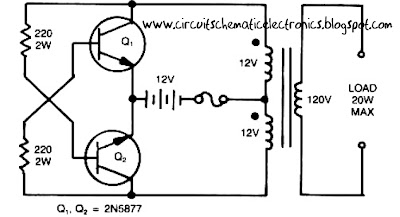
Transistor Q1 and Q2 use 2N5877 or similarity .If Q1 is faster and higher gain than Q2 , it will turn on first when aplly the input power and will hold Q2. Load current and the transformer magnetizing current the flows in the upper half of primary coil, and auto transformer supplies the base drive (two transistor) unti the transformer saturates.The transformator can use the 3A CT transformer an use the secondary coil for input and primary coil use to output, And input use the 12 volt secondary coil. Use 12 battery to power input , such as 12 V accu.
You can use the circuit at the time of death PLN electricity , using 12 volt battery or accu , you can turn n a fluorescent lamp or neon light.
Saturday, December 21, 2013
Very Simple Peak Indicator Circuit
This series is made to indicate that the amplifier has been given the maximum signal, the amplifier has the ability to be at its peak. if the lights do not mean the signal-plus volume. the way it works is the LED lights will light up when given a signal that more than 1.8 volts, the average amplifier will be saturated (maximum) if the signal was given more than this.

The circuit is very simple to the point that we forget that making a series of peak signal can in this way. circuit is mounted on the output tone control IC, master mixer output, or input power amplifier. This series does not impose on other circuits. survived the experiment!
Friday, December 20, 2013
Simple Inverter circuit with IC556 timer chip
This circuit is low power inverter , in this circuit only save a few components, about 9 parts. Voltage input from 10 volt to 16 volt DC into 60-Hz. And then voltage will be raised to about 115 V with power 25 W. The first section of IC 556 timer chip is wire as an astable oscilator with R2 and C1 setting the frequncy. The output is available at IC 556 pin 5. The second section is wired as a phase inverter. That output is available at IC 556 pin 9.
Schematic low inverter below :

The transformer use 120 V / 18 VCT unit that is connected backwards, so that it steps the voltage up rather than down. At resistor R3 and R4 keep output transistor Q1 and Q2 from loading the transistor. The transistor drive the transformer . The circuit can you use to supply lamp or other electronic devices.
Thursday, December 19, 2013
Simple Fluid Level Sensor
A very simple fluid lever sensor can be designed using this circuit diagram . This fluid level sensor electronic circuit project is very simple and can be used to control water pump or to activate /stop some devices when the sensor detects presence of water.
Simple Fluid Level Sensor Circuit diagram

This fluid level sensor circuit uses an ac sensing signal to eliminate electrolytic corrosion on the probes .The ac signal rectified is used to drive T1 transistor that drives a 12 volt relay , that can activate or stop some device . R2 resistor is used to modify the sensor sensitivity and can be replaced with a small variable resistor . MC104093B is a p channel quad 2 input NAND schmitt trigger and is pin to pin compatible with the CD4093 . The unused inputs must be tied to an appropriate voltage level , either ground or +12 volts (8,9,12 and 13) and the unused outputs must be left open (10 and 11) .
The circuit can be powered with an input voltage between 3 and 18 volts dc , but in our case the circuit use a 12 volts DC power source .
Simple Fluid Level Sensor Circuit diagram
The circuit can be powered with an input voltage between 3 and 18 volts dc , but in our case the circuit use a 12 volts DC power source .
Monday, December 16, 2013
Simple 100 Watt Inverter
This is a simplest circuit for 100 watt inverter for generating 220vAC from 12vDC. I say simplest because here in this inverter circuit a minimum number of components are used to design the schematic, which is quite difficult to make a circuit like this with further fewer components.
Simple 100 Watt Inverter Circuit Diagram

This 100W inverter circuit works great for small loads like a fan or 2-3 bulbs/lamps. In this circuit as IC1 we used a CD 4047 IC to generate 100Hz frequency (180 degree out of phase). CD 4047 IC is from Texas Instruments. It is mostly used as Astable/Monostable signal generator device. In this circuit it is triggered as astable multivibrator by the capacitor C1 between the Pin 1 and 3 of CD4047. And VR1 is used to adjust the frequency of signal.
Four 2N3055 transistors are used to amplify the pulse trains that are pre-amplified by two TIP122 transistors. There used three transistors for each side (half cycle), one TIP122 & two 2N3055 transistor to drive the output transformer (TX in circuit). Four 2N3055 transistors are used as driving transistor. An inverters maximum output power depends on two factors; one is the max current rating of transformer’s primary winding and other factor is the current rating of driver transistors.
Transformer: Use a 12v-0-12v, 10A step-down transformer in reverse. That’s mean secondary winding (12v-0-12v) will be the primary and primary winding (220VAC side) will be the secondary (output). So that it will worked like a step-up transformer. You can also use a 5A transformer instead of 10A, if you couldn’t have 10A. But the output power will decrease to 60 Watt.
+12VDC: A good quality 12V car battery could be used for DC 12V.
Parts list :
VR1 = 250K (Variable resistor/POT)
R1, R2 = 4.7K-1/4W Resistor
R3, R4, R5, R6 = 0.1R-5W
C1 = 0.022uF
C2 = 220uF-25V
D1 = BY127 Diode
D2 = 9.1V Zener Diode
Q1, Q4 = TIP122 Transistor
Q2, Q3, Q5, Q6 = 2N3055 Transistor
F1 = 10A Fuse
IC1 = CD4047
TX = 12-0-12V, 10A Step-down Transformer
VR1 = 250K (Variable resistor/POT)
R1, R2 = 4.7K-1/4W Resistor
R3, R4, R5, R6 = 0.1R-5W
C1 = 0.022uF
C2 = 220uF-25V
D1 = BY127 Diode
D2 = 9.1V Zener Diode
Q1, Q4 = TIP122 Transistor
Q2, Q3, Q5, Q6 = 2N3055 Transistor
F1 = 10A Fuse
IC1 = CD4047
TX = 12-0-12V, 10A Step-down Transformer
Thursday, October 24, 2013
Simple Operational Amplifier DC Motor Driver
Using a simple operational amplifier and some other common electronic components can be designed a very simple DC motor driver that can be used for a 200mA motor application . Rb sets the bias point for transistors Q1 and Q2.

Because Vbe(ON) varies greatly with temperature, a guardband is required to prevent Q1 and Q2 from conducting simultaneously. RB should be selected such that the transistors do not conduct until lM equals the op amp quiescent supply current, Isy . The transistors will begin to conduct at about Vbe (on) = 0.5V. In this project :
RB= [vbe(on)/(lSY+ Im)]= 0.5/(0.0025 + 0.0025)=100 ohms
To maximize voltage swing across the motor, V1 must be minimized. If at full load V1 = 0.2V with V+ = 15V and VBE1 = 0.8V, the voltage across the motor will be:
VM = (V+ - 2) - VBE1 - V1 = (15 - 2) - 0.8 - 0.2 = 12.0V Vin may be scaled with a resistive divider as:
VIN= (R1 + R2)/R2 With R1 = 240k and R2 = 10k, VIN =5 volt lM = 200mA.
RB= [vbe(on)/(lSY+ Im)]= 0.5/(0.0025 + 0.0025)=100 ohms
To maximize voltage swing across the motor, V1 must be minimized. If at full load V1 = 0.2V with V+ = 15V and VBE1 = 0.8V, the voltage across the motor will be:
VM = (V+ - 2) - VBE1 - V1 = (15 - 2) - 0.8 - 0.2 = 12.0V Vin may be scaled with a resistive divider as:
VIN= (R1 + R2)/R2 With R1 = 240k and R2 = 10k, VIN =5 volt lM = 200mA.
Sunday, October 20, 2013
Simple LED lights Circuit for Motorcycles
Lamp type LED has several advantages compared with the usual light when the applied on a motorcycle. In addition to more efficient battery when compared with normal hologen lamps, LED also has several other advantages, such as light more evenly and provide a luxurious feel to the vehicle.
The following are examples of simple creations that you can apply to decorate your motorcycle using the LED.
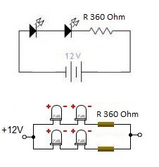
For this circuit is recommended only as a replacement motorcycle brake lights or city lights with the electrical source from the battery. Indeed in the market has many available variations of LED lights that can be used as brake lights or disco lights, but maybe some people would be proud if his own creative, hopefully circuit schemes that we present above can assist you in creating.
Monday, October 7, 2013
Simple RF Amplifier
This RF amplifier circuit diagram is a very simple and is designed to work for 10 meters band (26 ... 30 MHz) reserved for amateurs. By making this RF amplifier small power transmitters of 200 mW, can be transformed into a power transmitters reasonable, ranging between 2 and 3 W. The circuit is very simple. Network output filter suppresses noise by at least 55 dB.
Simple RF Amplifier Circuit diagram

Amplifier is suitable for almost all types of transmissions, because of the possibility of adjusting the drain current of FETs by P1. For linear applications (AM and BLU), drain current must be adjusted to 20 mA. If is used for FM-CW, P1 will be adjusted so that no current will not flow through the drain rest. For this case, the idle current is 200 mA and between 300 mA.
Coils are made on cases with a diameter of 9 mm. Care should be taken to wound as tight turns without any space between them. Coils should be made as follows: L1 = 12 turns enamelled 0.6 mm copper, L2 and L4 = 5 turns 1 mm enamelled copper, L3 = 8 1 mm enamelled copper coils.
Simple RF Amplifier Circuit diagram
Coils are made on cases with a diameter of 9 mm. Care should be taken to wound as tight turns without any space between them. Coils should be made as follows: L1 = 12 turns enamelled 0.6 mm copper, L2 and L4 = 5 turns 1 mm enamelled copper, L3 = 8 1 mm enamelled copper coils.
Sunday, October 6, 2013
Simple Nicad Battery Zapper circuit
This circuit is used to clear the nicad battery internal shorts in nickel - cadmium batteries. To operate this circuit , connect AC cable , then connect a Nicad battery to the output + , - and press PB (push button) for three second. See circuit below :
 |
| Nicad battery zapper |
Sunday, September 29, 2013
Mini and simple power amplifier circuits

What is the meaning of the picture above? The above picture is a miniature audio amplifier and very simple. Here I will give an audio amplifier schematic is very simple which only requires a few components only, can be seen under this scheme.
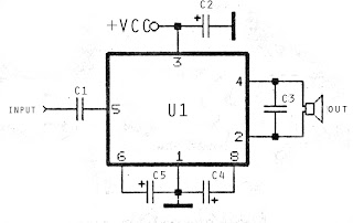
See from above scheme may occur to you, certainly cheap enough to make this amplifier and quite easy to make. The above simple audio amplifier circuit using an IC as the main amplifier and accompanied by other components. IC used is S1513, which requires a supply voltage ranging from 1.5 volts to 6 volts. And only 0.1 W output power with 4 ohm impedance. For a list components can be seen below.
Part list
C1 = 100nF
C2 = 100uF
C2 = 100uF
C3 = 3n3F
C4 = 1uF
C5 = 1uF
U1 = S1513
C5 = 1uF
U1 = S1513
Monday, September 23, 2013
Very Simple Pre Regulator
Present desire be there many period anywhere it is considered necessary to waste the P05 supply module from a upper voltage source. intended for case, if you lack to add balanced inputs to a power amplifier, next you need a +/-15V supply, but the amps supply voltage willpower survive much too far above the ground for the manager ICs.
This project is roughly speaking to the same extent unpretentious as they take place, and is very economical to build. It is designed in support of exactly this reason - to reduce the amplifier supply voltage to a safe significance for controller ICs.
The circuit it is very down-to-earth indeed. You desire need to make it to a hardly any simple calculations to determine the resistor value, but this is explained beneath.
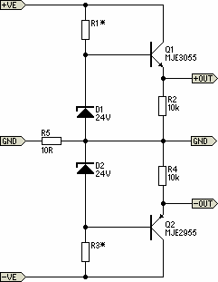
The circuit made known uses the 24V zener diodes (D1 and D2) to adjust the output voltage to a unimportant under 24V. This is a seamlessly safe input voltage in favor of standard 3-terminal regulators, and using this circuit long for provide even better guideline and supply clamor rejection at that time typical. Using MJE3055 and 2955 transistors will allow for supply voltages up to 70V quite safely, but they will need to take place mounted on a heatsink (with insulating washers).
The single-mindedness of R5 is to detach the foremost power amplifier ground from the supply, to prevent hum loops. The 10Ω resistor revealed motivation be fine in lieu of the vast majority of applications, but might need to remain untouched. This is up to you to research with if essential. I hint at so as to R5 ought to be 1W. R2 and R4 may perhaps be 1/4W before 1/2W resistors, and 1W zeners are recommended.
The lone calculation is to determine the regard in support of R1 and R3. original, quantify the power amp supply voltage (V1). The resistor value is calculated to provide a top figure zener current of 20mA, and this hope against hope ensure sufficient found current for the pass transistors representing up to 100mA before so output current by the side of ±15V.
V2 = V1 - 24 (someplace V1 is amplifier supply voltage, and a 24V zener is used)
R1 = R3 = V2 / 20 (R1 and R3 morals are arrived kΩ)
P = V2² / R1 (P is power dissipation of R1 and R3 in mW)
consent tos begin to have a supply voltage of ±56V meant for an pattern calculation ...
V2 = 56 - 24 = 32V
R1 = R3 = 32 / 20 = 1.6k (practice 1.5k)
P = 32² / 1.5 = 680mW = 0.68W (use 1W)
The dissipation in Q1 and Q2 could as well be located calculated, but you need to know the current drawn by the outdoor circuits. on behalf of instance, if the external circuitry draws 50mA, the transistor power dissipation is ...
Pt = V2 * Iext = 32 * 50 = 1600mW = 1.6W (it self-control need a slight heatsink)
Saturday, September 21, 2013
Simple Surround audio amplifier circuit based on the IC TDA7053
Perhaps the surround amplifier circuit below is an interesting circuit is made. For, making easy just by using the IC and electrolytic capacitor added 1 , we already can hear the strains of music with sound ( Front Left ,Right and surround Right , Left. In addition to listening to music , this amplifier is also very suitable for gamers who want good sound quality.

Minimum voltage requred 9 volts and maximum of 15 volts. Power Output of each speaker 10 Watt with 4 ohm impedance.
Wednesday, September 18, 2013
Simple Amplifier Schematic
This Circuit Use a IC BA515 for operation it. This is very simple Amplifier schematic , with only add 8 component , such as resistor and capacitor. Minimum voltage require 3 Volt , this also low voltage amplifier . And maximum voltage require 9 volt. Power output under 10 Watt with impedance 4 Ohm. This circuit is very suitable for small speakers.
See schematic below : 
- Check voltage on the circuit , wether or not the voltage.
- Check wether the components are soldered onto PCB properly.
- Check input and output wether working or not.
- Check input output cable , if there are disconnected , or a short circuit. Or input connected with ground.
Subscribe to:
Posts (Atom)