Showing posts with label battery. Show all posts
Showing posts with label battery. Show all posts
Saturday, October 18, 2014
Eliminator 1 5 Volt battery using LM317
This circuit is a battery eliminator 1.5 V, that is, a power supply of 1.5 volts, low consumption that takes as input the output of the USB PC or notebook. The power adapter is simple, it converts the voltage from 5V to 1.5V USB ports, using the popular LM317 IC and a few other components. To be exact this circuit uses only three components, one is the LM317, R1 = R2 = 470 ohm and 100 ohm.
Eliminator 1.5 Volt battery using LM317 Circuit Diagram


Tuesday, January 14, 2014
Universal Battery Charger Based on LM317
This universal battery charger is based on LM317 and has an adjustable regulated output voltage and also has an adjustable constant-current charging circuit that makes it suitable to use for charging most NiCad batteries and some other types of batteries . This LM317 universal battery charger can charge a single cell or a number of series-connected cells up to a maximum voltage of 18 V.
This universal battery charger circuit use just some common electronic components like LM317 regulator , operational amplifier and some 2n3055 power transistors .2n3055 power transistors Q1 and Q2 are connected as series regulators to control the battery chargers out¬put voltage and charge-current rate. The LM317 used as an adjustable voltage regulator supplies the drive signal to the bases of power transistors Q1 and Q2.

By turning the potentiometer R9 the output-voltage level will be modified. A current-sampling resistor, R8 (a 0.1-fi, 5-W unit), connected between the negative output lead and circuit ground.As the charging voltage across the battery begins to drop, the current through R8 decreases , then the voltage feeding pin 5 of U3 decreases, and the comparator output follows, turning Q3 back off, which completes the signals circular path to regulate the batterys charging current. The charging current can be set by adjusting R10 for the desired current.
This universal battery charger circuit use just some common electronic components like LM317 regulator , operational amplifier and some 2n3055 power transistors .2n3055 power transistors Q1 and Q2 are connected as series regulators to control the battery chargers out¬put voltage and charge-current rate. The LM317 used as an adjustable voltage regulator supplies the drive signal to the bases of power transistors Q1 and Q2.
By turning the potentiometer R9 the output-voltage level will be modified. A current-sampling resistor, R8 (a 0.1-fi, 5-W unit), connected between the negative output lead and circuit ground.As the charging voltage across the battery begins to drop, the current through R8 decreases , then the voltage feeding pin 5 of U3 decreases, and the comparator output follows, turning Q3 back off, which completes the signals circular path to regulate the batterys charging current. The charging current can be set by adjusting R10 for the desired current.
Sunday, December 22, 2013
12 Volt Nicad Battery charger
See this charger schematic below :

Tuesday, December 17, 2013
12 Volt Battery charger and also can Accu Charger
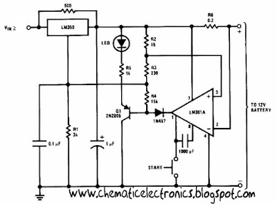
This 12 Volt Battery charger circuit best performance to charger 12 volt battery . Why this charger is best performance because this 12 Volt Battery charger quickly to recharger battery and shuts off at full charge. Initially , charging current is limited 2 A , but you can change for the transistor. As the battery voltage rises , current to the battery decreases , and when the current has decreases to 150 mA or 0.15 A this 12 Volt Battery charger switches to a lower float voltage , which prevents overcharge.
 |
| 12 Volt Battery charger Click to view Enlarge |
The 12 Volt Battery charger can be charger wet accu and dry accu , and to be make the accu old last longer. The output charger goes to 14.5 Volt. As the battery or accu approaches full charge , the charging current decreases and the output voltage is reduced from 14.5 Volt to about 12.5 volt, terminating the charging.
Sunday, December 15, 2013
Lead achid battery charger up to 3 battery
See battery charger circuit below :
 | |
| This is charger battery circuit |
Above circuit furnishes an initial voltage of 2.5 Volt per Cell at 25 degree celcius to rapidly charge a battery . the charging current decreases as the battery cahrges , and when the current drop 180 mA , the charging circuit reduces the output voltage to 2.35 V per cell, leaving the battery in a fully charged state.
Saturday, October 12, 2013
Battery Charger Using LTC4078
Using the LTC4078 standalone linear charger circuit you can design a very simple single-cell battery charger circuit for Li-Ion Li-Polymer battery . This LTC4078 battery charger circuit works from both wall adapter and USB inputs. This charger can detect power at the inputs and automatically select the appropriate power source for charging.
Battery Charger Using LTC4078 Circuit diagram

As you can see in the circuit diagram , this Li-Ion Li-Polymer charger requires few external components and you will need to apply just few equations ,to design a full work USB , wall adapter charger .
The charge current can be programmed up to 950mA from wall adapter input . IUSB pin is used for program the charge current for USB power that can be programmed by connecting a resistor to the ground.
The voltage on this pin can be used to measure the battery current delivered from the USB input using the following formula: IBAT = (VIUSB/RIUSB)*1000 . ITERM pin is the termination current threshold program that is set by connecting a resistor to ground. ITERMINATE is set by the following formula:
ITERMINATE =100V/RITERM ; RITERM =100V/ITERMINATE IDC pin is used for program the charge current for wall adapter power that is set by connecting a resistor to ground.The voltage on this pin can be used to measure the battery current delivered from the DC input using the following formula: IBAT = (VIDC/RIDC)*1000 .
The charge current delivered to the battery from the wall adapter or USB supply is programmed using a single resistor from the IDC or IUSB pin to ground and can be calculated using the following equations:
RIDC =1000V/ICHRG-DC , ICHRG-DC = 1000V/RIDC - Wall adapter
RIUSB =1000V/ICHRG-USB , ICHRG-USB =1000V/RIUSB – USB port.
Battery Charger Using LTC4078 Circuit diagram
As you can see in the circuit diagram , this Li-Ion Li-Polymer charger requires few external components and you will need to apply just few equations ,to design a full work USB , wall adapter charger .
The charge current can be programmed up to 950mA from wall adapter input . IUSB pin is used for program the charge current for USB power that can be programmed by connecting a resistor to the ground.
The voltage on this pin can be used to measure the battery current delivered from the USB input using the following formula: IBAT = (VIUSB/RIUSB)*1000 . ITERM pin is the termination current threshold program that is set by connecting a resistor to ground. ITERMINATE is set by the following formula:
ITERMINATE =100V/RITERM ; RITERM =100V/ITERMINATE IDC pin is used for program the charge current for wall adapter power that is set by connecting a resistor to ground.The voltage on this pin can be used to measure the battery current delivered from the DC input using the following formula: IBAT = (VIDC/RIDC)*1000 .
The charge current delivered to the battery from the wall adapter or USB supply is programmed using a single resistor from the IDC or IUSB pin to ground and can be calculated using the following equations:
RIDC =1000V/ICHRG-DC , ICHRG-DC = 1000V/RIDC - Wall adapter
RIUSB =1000V/ICHRG-USB , ICHRG-USB =1000V/RIUSB – USB port.
Wednesday, October 9, 2013
12V battery indicator level
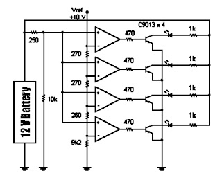
 The following sequence is useful to show the battery voltage (battery) 12 volts. Voltage level is shown with four lights led. To facilitate the reading of the led is arranged in a vertical array. Led top three chosen by the green LED while the lowest is selected the color red. If the battery voltage continues to decline (because of usage), the Led-Led will turn off sequentially from the top to the bottom.
Until if battery voltage is below 11.83 volts then only the red LED that lights up which means that the charge batteries are empty. Even this red Led will die if the stress continues to drop to below 11.5 volts. The working principle of this circuit is a comparison of battery voltage with a reference voltage.
Schematic Battery level indicator
Monday, October 7, 2013
USB powered battery charger circuit

At this time I will share about the series used in the usb to charge battery. Issued voltage 4.7 Volt to 5 Volt DC suitable for battery charge the phone, as well as other batteries.
Below is a circuit where the voltage is removed the usb on the computer will be strengthened by several components so that the voltage used to charge batteries more powerful and filtered, and will make it more durable and long lasting.
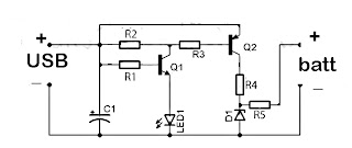
Part List :
R1 = 1 K
R2 = 330 R
R3 = 4K7
R4 = 300 R
R5 = 27R
D1 = 4.7 volt zener /1W
C1 = 100uF/16V
Q1 = BC548
Q2 = BC558A
R3 = 4K7
R4 = 300 R
R5 = 27R
D1 = 4.7 volt zener /1W
C1 = 100uF/16V
Q1 = BC548
Q2 = BC558A
Sunday, October 6, 2013
Simple Nicad Battery Zapper circuit
This circuit is used to clear the nicad battery internal shorts in nickel - cadmium batteries. To operate this circuit , connect AC cable , then connect a Nicad battery to the output + , - and press PB (push button) for three second. See circuit below :
 |
| Nicad battery zapper |
Friday, October 4, 2013
Faster Battery Charger Circuit 6 12 Volt with IC LM308 and LM317
This circuit is quickly charging the battery . If you need a faster charger ,this circuit is recomended to you . And this charger is low temperature , the temperatur is 5 degree celcius. Input Voltage is 15 Volt DC , and Output voltage to charging 6 -12V and you can adjust by the D1 (see schematic). And adjust the D1 to 50 mV greater VZ than D2 (see schematic). Couple the D2 to battery. This circuit operating by IC LM308 and LM317 and any other components. And you can use this circuit to charging Accu 6 or 12 Volt , dry or wet and other battery .
See this Schematic Circuit below :

Thursday, October 3, 2013
Ultra Fast Battery charger circuit
Ultra Fast Battery Chager for Nickel-Cadmium battery cells [NiCad] which will be discussed in this article is Fast NiCad Battery Charger, called the Ultra Fast Charger Battery Charger NiCad because it can make filling fast NiCad Batteries Cell. A battery charger in Desai has a fast charging capabilities such as Ultra Fast Battery Chager for Nickel-Cadmium battery cells [NiCad] on this article shall be equipped with some ability to protect the battery and charger circuit itself.
Feature owned by Ultra Fast Battery Chager for Nickel-Cadmium battery cells [NiCad]
- Autoshut-off, is the ability of the charger to stop charging current to a NiCad battery if the capacity NiCad battery is fully charged.
- Polarity Protection, with the existence of this capability so if there are mounting the battery on the charger upside yan can be known.
- Constant output voltage
- Output currents enough to fill some NiCad batteries at once in parallel.
- Short Circuit Protection, with the existence of this protection circuit so if there is short-circuit caused by a battery and a charger circuit itself will not damage the other parts are not damaged.
- Series Ultra Fast Battery Chager for Nickel-Cadmium battery cells [NiCad]

Image series above is a series of schematic drawings for Ultra Fast Battery Chager for Nickel-Cadmium battery cells [NiCad]. Ultra Fast Battery Chager for Nickel-Cadmium battery cells [NiCad] can be used for 8 to 10 NiCad batteries at once with 12 volt output voltage and max current is 3.5 A. The main components in the circuit of Ultra Fast Battery Chager for Nickel-Cadmium battery cells [NiCad] is UC3843 and MC34181. UC3843 chip is a voltage regulator and M34181 is a JFET OpAmp with characteristic low offset voltage, input impedance is very high. MC34181 serves as a voltage comparator.
Thursday, September 26, 2013
Universal battery charger with 12V source voltage
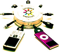
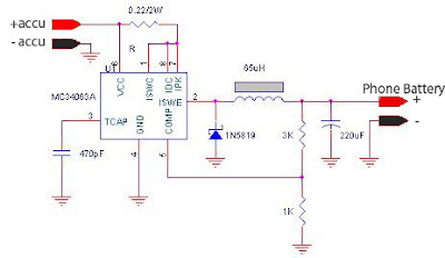
In this post I will share about using Accu source to charge batteries that can be used on any mobile brand, or can be called universal phone battery charger. Because the battery charger using a source of 12V, the charge accumulator can also be used in cars and others.
This will out charger circuit voltage of 5 volts DC, with input from at least 6 volt battery, and voltage inputs that have been tried till with 15 volts (more than it has not been tried, because the battery that tie the maximum output voltage is only 13.8 volts).
Wednesday, September 25, 2013
Circuit Battery Charging Regulator
The Charger Circuits / Circuit Battery - Charging Regulator is capable of charging a 12-Volts battery at up to six ampere rate. Other voltages and currents , from 6 to 600 Volts and up to 300 Ampere , can be accomodated by suitable component selection. When the battery voltage reches its fully charged level , the charging SCR shuts off , and a trickle charge , as determined by the value of R4 , continues to flow.
See Circuit Battery - Charging Regulator below :
See Circuit Battery - Charging Regulator below :
 |
| Circuit Battery - Charging Regulator |
You can use the circuit to charge :
- Cells battery
- Accu wet and dry
- Rechargeable battery
Monday, September 16, 2013
12 V battery charger with PUT
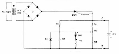
A short-circuit proof battery charger will provide an average charging current of about 8A to a 12V lead-acid storage battery. The Charger circuit has an additional advantage, it will not function nor will it be damaged by improperly connecting the battery to the circuit. With 220V at the input , the circuit comences to function when the battery is properly attached.The battery provides the current to charge the timing capacitor C1 used in the PUT relaxation oscillator.When C1 charges to the peak point voltage the PUT , the PUT fires turning the SCR on , which in turn applies charging current to the battery. As the battery charges , the battery voltage increases slightly which increases the peak point voltage of the PUT. The voltage on C1 increases until the zener voltage of D1 is reached , which clamps the voltage on C1 , and thus prevents the PUT oscillator from oscillating and charging ceases. The maximum battery voltage is set by potentiometer R2 which sets the peak point firing voltage pf the PUT . In the circuit shown , the charging voltage can be set from 10 V to 14 V - the Lower limit being set by D1 and the upper limit by T1.
Part List :
Resistor
R1 = 10K
R2 = 50K trim
R3 = 47K
R4 = 1K
Capacitor
C1 = 0.1uF
Diode , SCR , PUT
B1 = MDA990-1
D1 = 1N5240 10V
SCR = 2N5164
PUT = MPU131
Transformer , Inductor
T1 = Stepdown 220V to 14V
T2 = 11Z12 1:1
Thursday, September 12, 2013
USB Charger For Lithium Ion battery
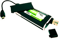
USB Battery Charger For Lithium Ion battery with the LM3622 is a series of lithium ion battery charger. This charger circuit operates using power from the USB source PC.
Current consumption of a series of USB Battery Charger For Lithium Ion battery with 400mA LM3622 is limited by R1, so it does not exceed the current maximum limit that can be given by a USB computer. Brains from USB Battery Charger For Lithium Ion battery with IC LM3622 , it is a national of having special technical specification charger for lithium ion batteries.
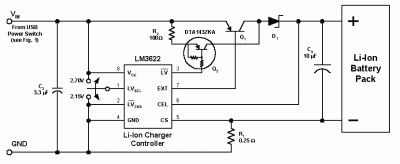
In a series of USB Battery Charger For Lithium Ion with LM3622 R1 0.25 Ohm value that serves to limit the charging current 400mA to the battery. Q2 and Q1 is the last part of the USB Battery Charger For Lithium Ion battery with the LM3622. In principle, USB Battery Charger For Lithium Ion with LM3622 identify the condition of the battery full charged battery voltage via pin 6 LM3622. USB Series Lithium Ion Battery Charger For LM3622 is equipped with a switch to select the battery that was in charge of 2.7 volts or 2.1 volts.
USB Charger For Lithium Ion battery
USB Battery Charger For Lithium Ion battery with the LM3622 is a series of lithium ion battery charger. This charger circuit operates using power from the USB source PC.
Current consumption of a series of USB Battery Charger For Lithium Ion battery with 400mA LM3622 is limited by R1, so it does not exceed the current maximum limit that can be given by a USB computer. Brains from USB Battery Charger For Lithium Ion battery with IC LM3622 , it is a national of having special technical specification charger for lithium ion batteries.
In a series of USB Battery Charger For Lithium Ion with LM3622 R1 0.25 Ohm value that serves to limit the charging current 400mA to the battery. Q2 and Q1 is the last part of the USB Battery Charger For Lithium Ion battery with the LM3622. In principle, USB Battery Charger For Lithium Ion with LM3622 identify the condition of the battery full charged battery voltage via pin 6 LM3622. USB Series Lithium Ion Battery Charger For LM3622 is equipped with a switch to select the battery that was in charge of 2.7 volts or 2.1 volts.
Subscribe to:
Posts (Atom)