Showing posts with label lm317. Show all posts
Showing posts with label lm317. Show all posts
Saturday, October 18, 2014
Eliminator 1 5 Volt battery using LM317
This circuit is a battery eliminator 1.5 V, that is, a power supply of 1.5 volts, low consumption that takes as input the output of the USB PC or notebook. The power adapter is simple, it converts the voltage from 5V to 1.5V USB ports, using the popular LM317 IC and a few other components. To be exact this circuit uses only three components, one is the LM317, R1 = R2 = 470 ohm and 100 ohm.
Eliminator 1.5 Volt battery using LM317 Circuit Diagram


Tuesday, January 14, 2014
Universal Battery Charger Based on LM317
This universal battery charger is based on LM317 and has an adjustable regulated output voltage and also has an adjustable constant-current charging circuit that makes it suitable to use for charging most NiCad batteries and some other types of batteries . This LM317 universal battery charger can charge a single cell or a number of series-connected cells up to a maximum voltage of 18 V.
This universal battery charger circuit use just some common electronic components like LM317 regulator , operational amplifier and some 2n3055 power transistors .2n3055 power transistors Q1 and Q2 are connected as series regulators to control the battery chargers out¬put voltage and charge-current rate. The LM317 used as an adjustable voltage regulator supplies the drive signal to the bases of power transistors Q1 and Q2.

By turning the potentiometer R9 the output-voltage level will be modified. A current-sampling resistor, R8 (a 0.1-fi, 5-W unit), connected between the negative output lead and circuit ground.As the charging voltage across the battery begins to drop, the current through R8 decreases , then the voltage feeding pin 5 of U3 decreases, and the comparator output follows, turning Q3 back off, which completes the signals circular path to regulate the batterys charging current. The charging current can be set by adjusting R10 for the desired current.
This universal battery charger circuit use just some common electronic components like LM317 regulator , operational amplifier and some 2n3055 power transistors .2n3055 power transistors Q1 and Q2 are connected as series regulators to control the battery chargers out¬put voltage and charge-current rate. The LM317 used as an adjustable voltage regulator supplies the drive signal to the bases of power transistors Q1 and Q2.
By turning the potentiometer R9 the output-voltage level will be modified. A current-sampling resistor, R8 (a 0.1-fi, 5-W unit), connected between the negative output lead and circuit ground.As the charging voltage across the battery begins to drop, the current through R8 decreases , then the voltage feeding pin 5 of U3 decreases, and the comparator output follows, turning Q3 back off, which completes the signals circular path to regulate the batterys charging current. The charging current can be set by adjusting R10 for the desired current.
Wednesday, October 23, 2013
LM317 Amplifier Circuit
You probably know with the purpose of LM317 IC is used being an changeable voltage manager, but did you know it can take place used as an audio amplifier? This is a taste A audio amplifier built with LM317 so as to delivers a utmost 1W audio power.
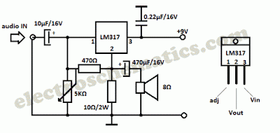
manipulate a worthy heatsink pro the LM317 IC and adjust the 5K inconsistent resistor so with the aim of you allow 4.5V on 10Ω resistor (otherwise LM317 pin 2, Vout).
Friday, October 4, 2013
Faster Battery Charger Circuit 6 12 Volt with IC LM308 and LM317
This circuit is quickly charging the battery . If you need a faster charger ,this circuit is recomended to you . And this charger is low temperature , the temperatur is 5 degree celcius. Input Voltage is 15 Volt DC , and Output voltage to charging 6 -12V and you can adjust by the D1 (see schematic). And adjust the D1 to 50 mV greater VZ than D2 (see schematic). Couple the D2 to battery. This circuit operating by IC LM308 and LM317 and any other components. And you can use this circuit to charging Accu 6 or 12 Volt , dry or wet and other battery .
See this Schematic Circuit below :

Tuesday, September 17, 2013
Solar Charger use IC LM317
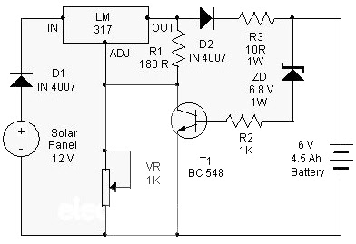
At this point is a Solar Charger Circuit to is used to charge information Acid otherwise Ni-album batteries using the solar energy power. The circuit harvests solar energy to charge a 6 volt 4.5 Ah rechargeable battery in favor of various applications. The stallion has Voltage and Current supervision and terminated voltage restrict sour facilities.
Circuit uses a 12 volt solar panel and a changeable voltage supervisor IC LM 317. The solar panel consists of solar cells each one rated on 1.2 volts. 12 volt DC is presented from the panel to charge the battery. Charging current passes through D1 to the voltage watchdog IC LM 317. By adjusting its Adjust pin, output voltage and current can subsist regulated.
 |
| Solar Charger use IC LM317 Schematic |
VR is placed amid the adjust pin and ground to provide an output voltage of 9 volts to the battery. Resistor R3 confine the charging current and diode D2 prevents discharge of current from the battery. Transistor T1 and Zener diode ZD conduct yourself having the status of a stop rotten switch at what time the battery is ample. Normally T1 is rancid and battery gets charging current.
After the terminal voltage of the battery rises over 6.8 volts, Zener conducts and provides station current to T1. It followed by turns on education the output of LM 317 to prevent charging. If you want to specific voltage / current output , you can replacing ZD on the circuit above.
Subscribe to:
Posts (Atom)