Showing posts with label and. Show all posts
Showing posts with label and. Show all posts
Tuesday, December 24, 2013
Stereo tone control with loudness and filter
Tone control circuit is used to adjust the tones before entering the amplifier. Tone control over equipped with a loudness and filter directly without using the switch to disconnected or connected. Part of his filter that is C1 and R1 from ground to input , and for his loudness on the R4 and C3 are connected to the input and then go to VR1. C2 and R3 go from ground to the input . After the input is set by volume or VR1 then procesed again by treebel ie C8 , R13 , R14 , and VR2 . Bass on R10 , R11, R12 , C7 ,C8 , and VR3. For supply voltages has been given a stabilization in Q3. See schematic below :
  |
| Click to view larger |
Part list :
R1 = 100K
R2 = 50K trim
R3 = 22K
R4 = 15K
R5 = 1K
R6 = 4K7
R7 = 330K
R8 = 330K
R9 = 3K3
R10= 5K6
R11= 8K2
R12= 5K6
R13= 1K
R14= 1K
R15= 50K TRIM
R16= 50K TRIM
R17= 330K
R18= 4K7
R19= 47K
R20= 1K
R21= 4K7
R22= 2K2
R23= 100R
R24= 22K
C1 = 15n
C2 = 15n
C3 = 560p
C4 = 4u7
C5 = 33u
C6 = 4n7
C7 = 39n
C8 = 39n
C9 = 4u7
C10=4u7
C11=470u
C12=100u
Q1 = C1815
Q2 = C828
D1 = Green Led
This tone control is suitable with 150W OCL power amplifier type 036.But the schematic is mono, if you need a stereo tone control you must duplicate the components and circuit.
 |
| Installation the stereo tone control |

Sunday, December 22, 2013
IR illuminator for Night Vision Tv Cameras and Scopes
This source uses LEDs and an astable oscillator to control the switch, duty-cycle, and effective IR illumination output.
Circuit Diagram

Circuit Diagram
Tuesday, December 17, 2013
12 Volt Battery charger and also can Accu Charger
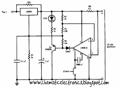
This 12 Volt Battery charger circuit best performance to charger 12 volt battery . Why this charger is best performance because this 12 Volt Battery charger quickly to recharger battery and shuts off at full charge. Initially , charging current is limited 2 A , but you can change for the transistor. As the battery voltage rises , current to the battery decreases , and when the current has decreases to 150 mA or 0.15 A this 12 Volt Battery charger switches to a lower float voltage , which prevents overcharge.
 |
| 12 Volt Battery charger Click to view Enlarge |
The 12 Volt Battery charger can be charger wet accu and dry accu , and to be make the accu old last longer. The output charger goes to 14.5 Volt. As the battery or accu approaches full charge , the charging current decreases and the output voltage is reduced from 14.5 Volt to about 12.5 volt, terminating the charging.
Friday, November 15, 2013
Accu charger use a diac and triac
This circuit can be used to charge Accu and cells battery , the circuit can has a very stable output that would make the battery last longer and maximize the added battery capacity. When charge was also quite fast , so it can optimize the time.

A diac is used in the gate circuit to provide a threshold level for firing the triac . C3 and R4 provide a transient suppression network. R1 , R2 , R3 , C1 , and C2 provide a hase - shift network for the signal being applied to the gate. R1 is selected to limit the maximum charging current at full rotation of R2.
Friday, October 25, 2013
Signal Tracer and Injector
A simple test circuit to fault find audio and radio equipment. Can be used to inject a square wave signal, rich in harmonics, or used with headphones as an audio tracer.
Signal Tracer and Injector Circuit diagram

a single pole double throw sitch is used to switch between inject and trace modes. The diagram is drawn in trace mode, the earpiece being connected to the collector of the last transistor. Both transistors are wired as emitter followers, providing high gain. DC blocking is provided by the 1n capacitor at the probe end, and the two stages are capacitively coupled.
When the switch is thrown the opposite way (to the blue dot) both transistors are wired as an astable square wave generator. This provides enough harmonics from audio up to several hundred kilohertz and is useful for testing AM radio Receivers.
Signal Tracer and Injector Circuit diagram
When the switch is thrown the opposite way (to the blue dot) both transistors are wired as an astable square wave generator. This provides enough harmonics from audio up to several hundred kilohertz and is useful for testing AM radio Receivers.
Thursday, October 24, 2013
System circuit not Minimum Evaluation Board AT89C2051 and AT89C4051
Maybe we are more familiar with the term Minimum System AT89C2051 circuit, but this time I present a circuit which is not only a series of Minimum System AT89C2051 but more than that.
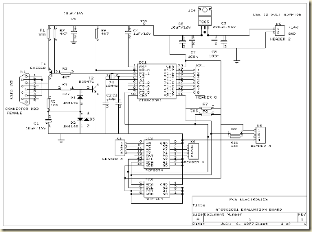
RS-232 interface, DB-9
Header for LCD display
I2C, PCF8574 I / O extender
AT24C04, I2C EEPROM
Next full text...
The circuit is more deserves to be called Evaluation Board AT89C2051 and AT89C4051. Some of the advantages of circuit Minimum System AT89C2051 / AT89C2051 and AT89C4051 Evaluation Board which I was present this time, hardware-hardware support below:
RS-232 interface, DB-9
Header for LCD display
I2C, PCF8574 I / O extender
AT24C04, I2C EEPROM
600W subwoofer audio amplifier with 20 channel mixer and parametric
This picture below is about my setup subwoofer amplifier with 20 CH mixer and parametric. This amplifier use transformer 10 ampere to supply the power and 3 ampere transformer use to supply mixer and parametric.Elco capacitor that i use for the transformer 10 A, only 10000uF numbered 2. The circuit of amplifiers that i use which is 600 watt mono subwoofer amplifier . And booster amplifier only use 2 Sanken transistors. See picture subwoofer amplifier assemblies below :
 |
| Looked over the side |
 |
| Front view |
 |
| Back top |


Wednesday, October 16, 2013
High and quality audio power amplifier with MJ15024G and MJ15025G
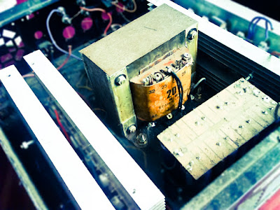
Spesification of this amplifier is high enough , and require a lot of expense to make this super-power amplifier. In the transformer using 20A and manufactered / branded ERA , ERA trafo is one of the best transformer , in addition to the power amplifier as well as power supply adapter , regulator , stabilizer , charger , etc. Because copper is intact , a strong iron and did not issue a frequency so that when the amplifier is turned on , output sound amplifier no buzzing. So if you in choosing a transformer , do not hesitate to use the transformer branded ERA.
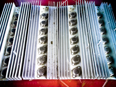
Above and below the picture is the end of the amplifier circuit, so-called booster amplifier. Picture above using 14 pairs of transistor MJ15025G and his partner MJ15024G . Transistor price range of $5 - $6 , has power output of 250W on each transistor , for more details , see datasheet of each transistor.
 |
| Click to view larger |
 |
| Installed transistor with resistor but still a mess |
Transistors MJ5025G and MJ15024G very fith with power amplifier 300 Watt subwoofer , 450 Watt , 600W , 750 Watt , 1050 Watt , 1200 Watt , and higher. The buffer and its driver using transistor not ic. For power schematic diagram can be found here.
Friday, October 4, 2013
Faster Battery Charger Circuit 6 12 Volt with IC LM308 and LM317
This circuit is quickly charging the battery . If you need a faster charger ,this circuit is recomended to you . And this charger is low temperature , the temperatur is 5 degree celcius. Input Voltage is 15 Volt DC , and Output voltage to charging 6 -12V and you can adjust by the D1 (see schematic). And adjust the D1 to 50 mV greater VZ than D2 (see schematic). Couple the D2 to battery. This circuit operating by IC LM308 and LM317 and any other components. And you can use this circuit to charging Accu 6 or 12 Volt , dry or wet and other battery .
See this Schematic Circuit below :

Sunday, September 29, 2013
Mini and simple power amplifier circuits
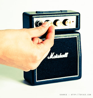
What is the meaning of the picture above? The above picture is a miniature audio amplifier and very simple. Here I will give an audio amplifier schematic is very simple which only requires a few components only, can be seen under this scheme.
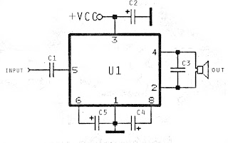
See from above scheme may occur to you, certainly cheap enough to make this amplifier and quite easy to make. The above simple audio amplifier circuit using an IC as the main amplifier and accompanied by other components. IC used is S1513, which requires a supply voltage ranging from 1.5 volts to 6 volts. And only 0.1 W output power with 4 ohm impedance. For a list components can be seen below.
Part list
C1 = 100nF
C2 = 100uF
C2 = 100uF
C3 = 3n3F
C4 = 1uF
C5 = 1uF
U1 = S1513
C5 = 1uF
U1 = S1513
Thursday, September 26, 2013
9 Sec Timer with LED Indication and Control Relay
The electronic circuit provides a visual time 9 second delay using ten LED before control by closing a 12 Vdc relay. That the reset switch has closed, IC 4017 decade counter will be reset to zero count which illuminates the LED driven from pin 3. IC 555 timer output at pin 3 will be high and the voltage at pins 6 and 2 of the timer will be a little less than the lower trigger point, or about 3 Vdc.
9 Sec Timer with LED Indication and Control Relay Circuit Schematic

That time the switch is opened, the transistor in parallel with the timing capacitor (22uF) is shut off allowing the capacitor to begin charging and the IC 555 timer circuit to produce an approximate one second clock signal to the decade counter. The counter advances on each positive going change at pin 14 and is enabled with pin 13 terminated low. When the 9th count is reached, pin 11 and 13 will be high, stopping the counter and energizing the relay. Longer delay times can be obtained with most capacitor or most resistor at pins 2 and 6 of the IC 555 timer.
9 Sec Timer with LED Indication and Control Relay Circuit Schematic
Tuesday, September 24, 2013
System circuit not Minimum Evaluation Board AT89C2051 and AT89C4051
Maybe we are more familiar with the term Minimum System AT89C2051 circuit, but this time I present a circuit which is not only a series of Minimum System AT89C2051 but more than that.
RS-232 interface, DB-9
Header for LCD display
I2C, PCF8574 I / O extender
AT24C04, I2C EEPROM
Next full text...
The circuit is more deserves to be called Evaluation Board AT89C2051 and AT89C4051. Some of the advantages of circuit Minimum System AT89C2051 / AT89C2051 and AT89C4051 Evaluation Board which I was present this time, hardware-hardware support below:
RS-232 interface, DB-9
Header for LCD display
I2C, PCF8574 I / O extender
AT24C04, I2C EEPROM
Transmitter and Receiver Infra Red Headphone

Transmitter and receiver circuit using infra red audio signal is applied to emit an audio signal and will received on a headphones. Making his series is not too difficult, the transmitter and receiver circuit scheme can be seen below.
 |
| Transmiter schematics |
 |
| Receiver schematics |
After the series finished, you can try to give the audio inputs on the transmitter and point the LED transmitter to the receiver. Maximum distance is a few meters may not be more than 10 meters, but you can listen to music without wires while using infra red.
image[link]
Thursday, September 19, 2013
PbS and PbSe detectors
Cal Sensors has two new families of lead salt infrared detectors as well as the introduction of a new digital drive board. The new single channel detector (SCD) and multichannel detector (MCD) families provide sensitivity for a variety of infrared sensing applications.
The SCD-13HV (single channel detector- high-value) PbS detectors are designed to meet requirements for high volume, cost-sensitive applications. SCD detectors provide sensitivity with typical D* from 9 x 10¹⁰ to 1.75 x 10¹¹ Jones across the one to three micron wavelength range. Performance varies with element size and window type.
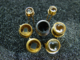
All SCD-13HV products support a glass window or lens configuration. Three element sizes are available in industry standard packages for easy integration. For applications where size is critical, such as portable test equipment, the SCD-13HV line offers a 1 by 1 mm detector in a TO-46 can. Where greater field-of-view or larger element sizes are important, 2 and 3 mm square detector sizes are available in TO-5 packages.
The new PbS and PbSe multi-channel detectors (MCD) provide sensitivity of 1.5 x 10¹⁰ Jones for detection of up to four distinct materials/gases. Covering one to five microns, the MCD product family provides channel isolation of >99.5 percent and a TO-5 footprint. An optional integrated thermistor within the MCD package optimizes temperature compensation for measurement precision. Co-locating the temperature sensor and detector material in a hermetically-sealed TO-5 package ensures they both ‘feel the same temperature variations and reduce potential effects of external environmental factors.
The four channel configuration offers opportunities for cost reduction and design simplification minimizing the need for multiple individual detectors and complex optics. System costs and footprints can be reduced up to 60 percent versus alternative single-detector designs. The technology is well-suited for a variety of applications including industrial and medical gas analysis, as well as auto and aviation emissions testing. It is useful for environmental applications such as stack monitoring, greenhouse gas analysis and overseeing air quality in confined spaces including tunnels and underground structures.
Though customizable for different applications across the one to five micron infrared spectrum, the MCD-15 line is available in a standard four-channel configuration with four discrete optical bandpass filters. This configuration supports CO, CO2 and hydro-carbon (such as methane) gas analysis.
Cal Sensors new Digital Drive Board optimizes signal levels for Cal Sensor´s one to four channel detectors. Designed with a socket that accepts Cal Sensors standard one to four-channel detectors, the digital board provides all the electronics necessary to drive the sensor, digitize the output and connect via USB to a computer or microprocessor. Supporting PbS and PbSe detector technologies, these drive boards were created to accelerate prototyping and product development.
source:[link]
Wednesday, September 18, 2013
Transmitter and Receiver Infra Red Headphone
Transmitter and receiver circuit using infra red audio signal is applied to emit an audio signal and will received on a headphones. Making his series is not too difficult, the transmitter and receiver circuit scheme can be seen below.
|
| Transmiter schematics |
|
| Receiver schematics |
After the series finished, you can try to give the audio inputs on the transmitter and point the LED transmitter to the receiver. Maximum distance is a few meters may not be more than 10 meters, but you can listen to music without wires while using infra red.
image[link]
Thursday, September 12, 2013
78XX and 79XX stabilizer circuit with mini PCB design
Here I present the stabilizer circuit of the IC 78XX and 79XX commonly used for voltage stabilization with a mini PCB design , and practical. In the picture above is looking from top the PCB, with a width of 2 cm and 5 cm height. For input voltage can be directly through the AC because ive put it four rectifier diodes are then forwarded to the Elco and IC , that has a stable output in accordance with IC series. What if the IC series 7805 and 7905 , the output voltage of 5 Volts. If the series IC 7812 and 7912 then the output voltage of 12 volts , and so on. See circuit schematic below :


Part List :D1,D2,D3,D4 = 1N4007C1,C2 = 1000 uF/50VC3,C4 = 470 uF/50V
IC1 = 78xx series
IC2 = 79xx series
And this is PCB design look from bottom :

PCB design by SIGMA4-Madiun
Subscribe to:
Posts (Atom)