Showing posts with label 9. Show all posts
Showing posts with label 9. Show all posts
Thursday, October 17, 2013
9 20 Volt amplifier circuit
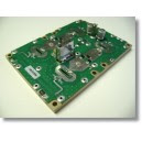 For this time I will post the scheme following an amplifier of the IC KA2203, SN16975, TBA820, UL1482P. Which has 4 Watt power output with 4 Ohm impedance. At least 8 Volt supply voltage and a maximum of 20 volts.
Part List
R1 = 100K
R2 = 56R
R3 = 56R
Use 1/2 W resistor
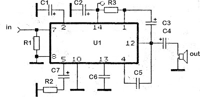
C1 = 47uF
C2 = 100uFC3 = 100uF
C4 = 470uF
C5 = 470pF
C6 = 0.22uF
C7 = 100uF
U1 = KA2203 , SN16975, TBA820, UL1482P

Thursday, September 26, 2013
9 Sec Timer with LED Indication and Control Relay
The electronic circuit provides a visual time 9 second delay using ten LED before control by closing a 12 Vdc relay. That the reset switch has closed, IC 4017 decade counter will be reset to zero count which illuminates the LED driven from pin 3. IC 555 timer output at pin 3 will be high and the voltage at pins 6 and 2 of the timer will be a little less than the lower trigger point, or about 3 Vdc.
9 Sec Timer with LED Indication and Control Relay Circuit Schematic

That time the switch is opened, the transistor in parallel with the timing capacitor (22uF) is shut off allowing the capacitor to begin charging and the IC 555 timer circuit to produce an approximate one second clock signal to the decade counter. The counter advances on each positive going change at pin 14 and is enabled with pin 13 terminated low. When the 9th count is reached, pin 11 and 13 will be high, stopping the counter and energizing the relay. Longer delay times can be obtained with most capacitor or most resistor at pins 2 and 6 of the IC 555 timer.
9 Sec Timer with LED Indication and Control Relay Circuit Schematic
Subscribe to:
Posts (Atom)