Showing posts with label circuit. Show all posts

Wednesday, January 29, 2014

Fish caller electronics circuit

For those of you who like fishing, this circuit is very suitable for you implement, because it can call the fish and collect a lot of fish so it is easy to provocation and get a lot of fish. Vibrations are excluded from this circuit reaches a distance of several meters in a circle. You can use the river, of where many fish that are easy to find except at sea the waves are fast , so this circuit will not work because it lost by the waves of the sea .Actually , can also be used at sea was calm but the water should not be too choppy.

Part List:
C1   = 10nF
C2   = 47uF/16V
VR1= 5K
R2   = 470R
S1    = Switch On/off
Q1   = BC160
T1   = Transformator Output (OT)
G1  = 3V battery

How to use  the Fish caller circuit :
Ater the circuit is finished and sounds biased, then put inside the bottle and sealed for later when inserted in the water is not damged. After the circuit was put into bottles and then put into water, wait several seconds after the switch on/off button. After this circuit work the fish will come and surround this tool. And when its like that then its time to fishing.
Next full text...

Tuesday, January 28, 2014

Circuit 150W amplifier with active crossover

stereo amplfiier with crossover
Series 150W Amplifier With Active Crossover Series 150W Amplifier with Active Crossover is very interesting. Actually, this circuit uses 4-channel power amplifier chip. Well, as an Active Crossover here we use also a chip that can separate the tone of the bass, midrange and treble, the output from the Active Crossover can be directly amplified by power amplifier.

Power Chip 4-channel amplifier that we use is SANYO LA47536 who have power outputs up to 150W, while for Active Crossover (Active Crossover) we use the LF353 from National Semiconductor.

stereo active crossover amplifier
Next full text...

Saturday, January 25, 2014

TV Protect Circuit Dead or Damaged
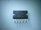
Television set equipped with a circuit protector, then there are several possibilities that could occur if there is a problem on one of the circuits. Protect circuit horizontal part - When turned on the horizontal plane will live for a while, but then died again. At the time of death when measured on the horizontal driver indicates that no drive signal. If the power jack unplugged then try to turn on again then repeated a similar incident will happen again. But if if the base of the transistor or transistor try to open removable drive signal was viable.

Protect circuit of microcontroll - If checked the voltage at pin microcontrol power on-off control, power control is turned on when the plane going "on" for a while then back "off". If you unplugged the power jack will power "on" again, but briefly and then keep coming back "off". On certain models sometimes die when the aircraft was marked with the blazing LED indicators blink. Protect circuit tube - aircraft can be turned on but a dark raster. 
IC protek protek rusak
Protect IC

Tested voltage raster screen can be raised to normal flame or flame a horizontal line. Protect circuit the power supply - if enabled aircraft B + voltage of power supply there for a while but then lost or drops. Or the power supply voltage drops and there is but little rocking voltage, which is caused due to power supply to the death over and over again and again. There are models of televisions that do not use the protector system at all, there is only one system that uses a surge protector, but there are also some systems which use a surge protector as well. System protectors are made available for specific purposes. Keep track of the damage that led to protect circuit is sometimes difficult, because it always turns itself off the plane before we can make measurements. By getting to know a wide range of system protectors and understand how it works it will help overcome these difficulties.

Various kinds of protectors television system:
  • Protectors x-ray
  • Vertical Protectors
  • Protectors B + over current (OCP)
  • Protectors B + over voltage (OVP)
  • ABL Protectors
  • Supply voltage surge protector (if short or broken)
  • Protectors white balance
  • Protectors circuit power supply (SMPS)

Next full text...

Monday, January 20, 2014

Atmel microcontroller Easy Downloader Circuit

Easy Downloader Circuit
Atmel microcontroller series AT89Cxx51 Easy Downloader is one of the downloader that is often used to write data to program the Atmel microcontroller AT89CXX51. Easy Downloader AT89Cxx51 ATMEL microcontroller is using the serial port as a channel of communication with the computer. 


Easy Downloader ATMEL Microcontroller AT89Cxx51 can be used to program Atmel AT89CXX51 in parallel. Atmel microcontroller series AT89Cxx51 Easy Downloader is quite simple to make your own because the components necessary to membutanya not complex. Atmel microcontroller series AT89Cxx51 Easy Downloader do not support the serial programming microcontrollers ISP. In the article Easy Downloader ATMEL Microcontroller AT89Cxx51 only displays images Easy Downloader Microcontroller series from Atmel AT89Cxx51 only and are simple.
Next full text...

Sunday, January 19, 2014

Megabass Circuit with TL072

The following is megabass circuit schematic (Mega Bass Circuit) . The megabass circuit is a modified Baxandall tone control with no bass cut and no treble control. It boosts frequencies from about 30Hz to 160Hz can boost by 14dB.

Megabass Schematics

Note:
The input capacitor can be replaced with a .01uf cap if you wish.
The 10pf capacitor is optional and will start rolling off everything over 15kHz. 5pf will double this to 31kHz.
The tone control requires a low impedence input. If you already have a low impedence input, the input buffer can be removed. However, the output is inverted.
The opamp is not critical. A 4558 would be just fine.
I do not show the parts for the +4.5 reference. Here is the +4.5 voltage divider I used.
IC A4558 Pinning

The A4558 is a monolithic Integrated Circuit designed for dual operational amplifier.

Absolute maximum ratings of A4558 Ap-amp
Supply voltage VCC 20 or ±10 V
Differential input voltage VIND 20 V
Input voltage VIN ±10 V
Power Dissipation PD 300 mW
Operating temperature Topr -45 ~ +85 °C
Storage temperature Tstg -55 ~ +150 °C
Next full text...

Saturday, January 18, 2014

Reducing Treble tone circuit

Treble reducer circuit above is an example of a simple circuit and is suitable to be used as experimental material and analysis of the workings of the circuit. 


As I mentioned earlier the bass reducer series, this series actually has the same working principles with a series of bass reducer. Where these circuits utilize capacitors nature of the charge and discharge. The difference of the damping function obtained from the difference of the capacitor. If the series bass reducer series capacitors are mounted on the op-amp input lines, while in this treble reducer series capacitors are mounted parallel with the strengthening of the op-amp prisoners. Installation of this circuit has a parallel in the work analysis in contrast with the installation of the series on a series of bass reducer. The difference is that the installation of the series, so we URLs that are easy to understand how a wire working capacitors for high frequency signal, so with high frekuesni so automatic signal to be passed to the output terminal by a capacitor. But if we put a parallel between the output capacitor with the terminals, then automatically because the capacitor is considered as a wire so the voltage on the capacitor is near 0 volts, so the output voltage will also follow the voltage on the capacitor because they connect parallel. As with the low frequency signal, the capacitor is considered open and makes voltage wire that fell to him is to approach the input voltage. To understand how the capacitor can be regarded as a wire or an open switch I mentioned in my post about the working principles of capacitors and a series of bass reducer.

Indeed, when examined in detail, not only the capacitors that play a role here but the component resistors and op-amp also affect. But I can confirm that the main function is performed by a capacitor reduction. Series resistors are intended to be installed that will flow into the capacitor can be adjusted so that it influences the charge and discharge the capacitor will make the appropriate damping.

Take a look at the picture above the treble reducer circuit and also the image output signal. There are two function generator as input and has a signal with different frequencies. The first signal of amplitude 1 volt and low frequencies, the two signals with an amplitude of 1 volt and with high frequency. At the time of our input select switch position to the relationship with the input low frequency signal, the signal output will be nearly equal to the input signal such as no change. Whereas if we switch position to link high-frequency input signal then the output signal amplitude will be damped near 0 volts.

Example treble reducer circuit is very simple and can you develop more in accordance with the desires and your needs. At least with understanding the working principle of this circuit we can apply a time when we are required to perform the function of damping trebele.
Next full text...

Monday, January 13, 2014

Wireless receiver microphone circuit

Wireless receiver microphone circuit
Just as in the transmitter circuit, the series of FM Wireless Microphone Receiver Hi Fi also uses an FM audio receiver module. Module used in the circuit FM Wireless Microphone Receiver Hi Fi has a good feture, namely audio FM receiver module has a function that is able to muffle the noise squel. Audio FM receiver module that is used in FM Wireless Microphone Receiver Hi Fi also does not require a lot of supporting components in the RF signal reception.


Audio FM receiver module only requires a 5 volt DC voltage source and a potentiometer P2 to set the threshold level of noise that will be muffled. Voltage source to an audio FM receiver module is also to go through the regulator is good, because if the quality of resources kuran it will generate noise. At the output line installed capacitors C3 and C4 as a couple and compensator for output in accordance with the amplifier or mixer (100mV rms).


receiver microphone circuit


Part Series FM Wireless Microphone Receiver Hi Fi
To provide an output signal according to the needs and stable output signal audio FM receiver module on FM Wireless Microphone Receiver Hi Fi is fed to an audio preamplifier which uses IC TLC272. Levelk audio signal set by potentiometer P1. As a voltage regulator for power source circuit FM Wireless Microphone Receiver Hi Fi LM7805 regulator IC is used.


Next full text...

Friday, December 27, 2013

Car Mobile Phone Charger Circuit

Car Mobile Phone Charger Circuit
Cellphone battery charging process when were done traveling is a big problem. Because when traveling source of power supply is generally difficult to find. If you turn on your phone then the battery continuously over time will run out within a period of five to six hours and eventually mobile phones unusable. Here is described a series of simple charger that will increase battery life two to three hours.


In principle, the charger uses a series of Limited Voltage Current Source. Generally requires cellphone battery voltage 3.6 - 6 volts DC and currents 180-200 mA to perform the charging process. Cellphone battery usually consists of three NiCd battery cells, and each cell has a voltage of 1.2 volts potential. At the speed - average low flows required to charge mobile phone battery about - about 100mA.

Car Mobile Phone Charger Circuit schematics

In this series there is a 12V voltage source consists of 8 regular battery cells (each cell 1.5 Volt) able to supply current at 1.8 A which is connected with output terminals.

The circuit is also able to monitor the battery voltage level which is in charge. And will automatically cut off the charging process when the output terminal detects a certain battery voltage level predetermined. Timer IC NE555 is used to charge and monitor the voltage level in the battery, Pin 5 (IC1) as the control voltage using a reference voltage zener voltage 5.6Volt. Voltage at Pin 6 as the threshold set by VR1 and the voltage at Pin 2 as the trigger is set by VR2.

When the cellphone battery is connected in series (the Charging Process) applied voltage on PIN2 (IC1) as a trigger would be below the value 1 / 3 Vcc and will cause the Flip-Flop in IC1 will ON and on Pin 3 (IC1) will be high (Cause transistor T1 saturation.). When the battery is full (Full Charge) then the voltage will rise and the voltage on the PIN2 (IC1) will be above the level of trigger point threshold. This will cause the Flip Flop OFF and the output will be low (transistor T1 causes the cutoff) and indirectly also the charging process will stop.

Pin 6 (Threshold IC1) is set at 2 / 3 Vcc by using VR1, transistors T1 which is used to increase the charging current. R3 value is very important to provide the charging current, by setting the value of R3 to 39 ohms then the charging current supplied approximately 180mA. This circuit can be built on any type of PCB (General Purpose PCB) for the calibration process using the DC voltage level cutoff Variable Power Supply. Connect the output terminal circuit with Variable DC Power Supply and set on 7 volts. Adjust VR1 in middle position and slowly adjust VR2 until LED1 OFF, this indicates Low Output. LED1 should turn on when the DC Variable Power Supply voltage is reduced below 5V. LED1 Status flame shown in the table below. Closed circuit with plastic casing and use a suitable connector for connecting to the Battery for Mobile.
Next full text...

Tuesday, December 24, 2013

Audio Amplifer Circuit 230W With MOSFET IRFP240 9240

Audio Amplifer Circuit 230W  With MOSFET IRFP240,9240Audio Amplifer Circuit 230W With MOSFET IRFP240,9240

Here is simple LED-power audio amplifier ambit with MOSFET amplifier TL071C and 2 may be up to 45 W into 8 ohms. For MOSFET IRFP240 and IRFP9240 are acclimated assurance with accessory can now be these modification.

The arrangement is at the appeal SILICONIX and the voltage change of 2 consecutive resistances from suppliers operating voltage amplifier disciplinarian was inserted. MOSFET charge be army on at atomic one condenser 1K / W.

Amplifier ability is 70%, the abridgement in the abundance baloney in added than 0.2% at 20 Hz at 8 ohms and 10W. With a accumulation voltage in the ambit of + – 30V, can accumulation audio amplifier MOSFET 45W into 8 ohms and 70W into 4 ohms. Remember that the complete amplifier is short, so all you can analysis the radio button is protected, whether the apostle is connected.

Next full text...

Monday, December 23, 2013

Simple Inverter Circuit from 12 V up to 120V elevated
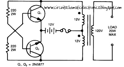
This is a simple 120 V : 24 V , center - tapped (CT) control transformer and four additional components can do the operation. This circuit outputs a clean about 120 volt - 200 volt at 60 Hz and can supply up to 20 Watt. The circuit is self starting and free running. See this simple inverter circuit below :
Simple Inverter Circuit from 12 V up to 120V elevated

Transistor Q1 and Q2 use 2N5877 or similarity .If Q1 is faster and higher gain than Q2 , it will turn on first when aplly the input power and will hold Q2. Load current and the transformer magnetizing current the flows in the upper half of primary coil, and auto transformer supplies the base drive (two transistor) unti the transformer saturates.The transformator can use the 3A CT transformer an use the secondary coil for input and primary coil use to output, And input use the 12 volt secondary coil. Use 12 battery to power input , such as 12 V accu.


You can use the circuit at the time of death PLN electricity , using 12 volt battery or accu , you can turn n a fluorescent lamp or neon light.
Next full text...

Sunday, December 22, 2013

Hearing aids circuit

Hearing aids circuitCommercially available hearing aids are expensive. Here is a cheap hearing aid circuit that uses only four transistors and some passive components. In moving the power switch S to on position, the condenser microphone detects the sound signal, which is amplified by transistor T1 and T2.

Hearing aids circuit schematics
Now the amplified signal through coupling capacitor C3 to the basic Transistor T3. Signal further amplified by T4 to a PNP transistor drive low impedance earphones. Capacitors C4 and C5 is the power supply decoupling capacitor. This circuit can be easily installed in small, general purpose PCB or Vero board. It operates off of DC supply of 3V. For this, You can use two small 1.5V cells. Continue to switch S to the state off when circuit is not used. To increase the sensitivity of the condenser microphone, the house in a small tube. This fee circuit around Rs 65.
Next full text...

Saturday, December 21, 2013

LED Flasher Circuit Using 555 Timer IC

This is a simple LED flasher project that uses a common 555 timer IC for its operation. It is configured as an astable mode which means that its output is a square wave oscillator. Two LEDs are connected to its output in such a way that when one LED is ON, the other LED will turn OFF. 

It uses only 10 simple parts that are easily available at any electronic shops. Capacitor C2 charges exponentially through resistors R1, R2 and the resistance of the trimpot. When C2 has charged to about 2/3 VCC it stops charging and it discharges to about 1/3 VCC through R2 and the trimpot resistance via pin 7. This is the standard operation of a 555 timer. When a Vcc of 5 V to 15 V DC is applied to the circuit, the LED will start to flash.
The frequency of the flashing can be changed by varying the resistance of the potentiometer or trimpot. Parts List The parts list of the simple LED project is as shown below.

Next full text...

Automatic Water Pump Controller Circuit
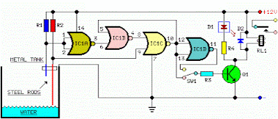
Automatic water pump controller is a series of functions to control the Automatic Water Pump Controller Circuit in a reservoir or water storage. As the water level sensor made with a metal plate mounted on the reservoir or water tank, with a sensor in the short to create the top level and a detection sensor for detecting long again made the lower level and ground lines connected to the bottom of reservoirs or reservoir. The series of automatic water pump controller is designed with 2 inputs NOR by 4 pieces and relay that is activated by the transistor. Automatic water pump circuit requires +12 VDC voltage source and can be used to control the water pump is connected to AC power . Here is the complete series of pictures.


Series Automatic Water Pump Controller 

Automatic Water Pump Controller Circuit


List Component Automatic Water Pump Controller 
R1 = 15K 
R2 = 15K 
R3 = 10K 
R4 = 1K 
D1 = LED 
D2 = 1N4148 
Q1 = BC337 
IC1 = 4001 
SW = SPDT Switches 
Relay RL1 = 12V 

The working principle series of automatic water pump controller above is. At the time the water level is below both sensors, the output IC1C (pin 10) will be LOW, Kemudin when the water began to touch the lower level sensor, the output IC1C (pin10) remains LOW until the water touches the sensor level above, then the output IC1C (pin 10) going HIGH and active relay through Q1 and turn on the water pump to meguras reservoir. At the muli down and water level sensors for water untouched MKA IC1C output (pin 10) remains HIGH until the new water untouched semuasensor IC1C output (pin 10) LOW and water pump died. The series of automatic water pump controller is equipped with SW1 which serves to reverse the logic of drains (the output of IC1C) and the concept of water supplied (output dri IC1D). When SW1 is connected to IC1D the water pump will turn on when the water does not touch all the sensors and will die when all the sensors tesentuh water. Automatic water pump controller can be used to fill or drain the water according to which mode is selected via SW1.
Next full text...

Very Simple Peak Indicator Circuit


This series is made to indicate that the amplifier has been given the maximum signal, the amplifier has the ability to be at its peak. if the lights do not mean the signal-plus volume. the way it works is the LED lights will light up when given a signal that more than 1.8 volts, the average amplifier will be saturated (maximum) if the signal was given more than this. 


The circuit is very simple to the point that we forget that making a series of peak signal can in this way. circuit is mounted on the output tone control IC, master mixer output, or input power amplifier. This series does not impose on other circuits. survived the experiment!
Next full text...

Friday, December 20, 2013

Simple Inverter circuit with IC556 timer chip

This circuit is low power inverter , in this circuit only save a few components, about 9 parts. Voltage input from 10 volt to 16 volt DC into 60-Hz.  And then voltage will be raised to about 115 V with power 25 W. The first section of IC 556 timer chip is wire as an astable oscilator with R2 and C1 setting the frequncy. The output is available at IC 556 pin 5. The second section is wired as a phase inverter. That output is available at IC 556 pin 9.
Schematic low inverter below :
 

The transformer use 120 V / 18 VCT unit that is connected backwards, so that it steps the voltage up rather than down. At resistor R3 and R4 keep output transistor Q1 and Q2 from loading the transistor. The transistor drive the transformer . The circuit can you use to supply lamp or other electronic devices.
Next full text...

Thursday, December 19, 2013

LED Circuit with Timer 555


This circuit LED reproduces the first LED sequence at this time used by FISA on behalf of Formula single racing. It may perhaps be alive used with slot car sets (such for example HO shin up AFX/Life Like/Tyco sets) or else means of communication controlled cars. IC1, a 555 timer IC, is used as a watch pulse generator. Its output is fed via NAND gates IC2a and IC2c to IC3, a 4024 binary counter. IC2b inverts the O4 output of 4024 binary counter IC3. originally, IC3 is reset and all its outputs are low, together with O4, which causes IC2b to present-day a rational climax to the pin 8 input of IC2c which after that passes pulses from the 555 timer circuit to the clock input of the 4024. IC3 then begins together with.

LED Circuit with Timer 555

Following the count has reached binary 1111, the subsequently pulse sends the O4 output of IC3 high, which disables IC2c and IC3 stops with. The four used outputs of IC3 are connected to a resistor ‘ladder’ which acts to the same degree a clear-cut digital to analog convert-er (DAC). As the count increases so does the voltage produced by the side of the top of the ladder and this is connected to the inverting inputs of four comparators inside IC4 (an LM339) and to IC5, which is a 741 op amp furthermore connected while a comparator.

The categorical inputs of the comparators are connected to the taps of a voltage dividing wall, with the drumming voltages settle on using VR1, a 100kO trimpot. As IC3 counts, the rising stepped voltage from the DAC ladder switches the comparators on clothed in sequence, preliminary with IC4d and working up to IC5. in the same way as both comparator is curved on, its pair off of LEDs is lit; former LEDs 1 & 2, next LEDs 3 & 4 and so on. as soon as all five pairs of LEDs are lit, the then pulse from IC1 moves the binary count of IC3 to 10000, so the DAC voltage drops back to zilch and all LEDs are extinguished. by the same spell, with too stops, for the reason that the area of high pressure on O4 causes IC2c to check extra gate pulses. The circuit in that case remains reserve until the counter is reset by urgent pushbutton switch S1. This allows a recent sequence to initiate.

Next full text...

Wednesday, December 18, 2013

8 Relay Control Circuit

8 Relay Control Circuit
R1-8=4.7 Kohms T1-8= BD139 (R1-8=15 Kohms if T1-8=BD679)
RL1-8=6V-24V dc Relay D1-8=1N4148
8 Relay Control Circuit 

Next full text...

Tuesday, December 17, 2013

Running Light circuit uses a CMOS 555 timer
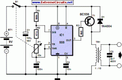

A Transcutaneous Electrical Nerve Stimulation (TENS) device is, put bluntly, a machine for giving electric shocks. The author was prescribed such a device on loan by his orthopaedic specialist. The unit has a large number of programmes, of which he used only one. Measuring the signals at the output of the device in this mode revealed damped oscillations at a frequency of approximately 2.5 kHz, with a repetition rate of approximately 100 Hz.
Running Light circuit uses a CMOS 555 timer

How hard can it be to make such a device ourselves? The simple circuit uses a CMOS 555 timer to produce a brief pulse which feeds a 1:10 miniature transformer. Together with a 4.7 nF capacitor the transformer makes a parallel resonant circuit: the resonance leads to a considerable increase in the output voltage. The pulse width can be adjusted using a potentiometer, here shown combined with the on-off switch. Wider pulses produce higher output voltages. Since a peak voltage of up to 200 V can be produced, the transformer must have adequate insulation: Conrad Electronics type 516260-62 is suitable. A low-cost phono socket at the output gives reliable connection to the electrode cable.

The adhesive electrodes shown in the photograph (disposable and permanent types are available) can be obtained from pharmacies and medical suppliers. They generally have connectors compatible with 2 mm banana plugs, and so it is possible to make up the necessary cable yourself. To treat responsive parts of the body, such as the arm, the potentiometer need not be turned up far to obtain the necessary sensation. Less sensitive parts, such as the knee or foot, need a rather higher voltage and hence a correspondingly higher potentiometer setting.

Author: Klaus Rohwer – Copyright: Elektor Electronics Magazine
Link:http://www.extremecircuits.net/2010/06/transcutaneous-electrical-nerve_03.html
Next full text...

PT2399 Digital Echo Circuit

PT2399 digital Echo circuit
Digital Echo Processor IC PT2399 is using CMOS technology in audio purposes. Digital Echo Processor PT2399 is implementing the system in the process of ADC and DAC audio repro echo.


Digital Echo Processor PT2399 has a high sampling frequency and 44K memory. Digital Echo Processor PT2399 to repro echo digital audio system of repro VCO delay time system that can be arranged. Digital Echo Processor PT2399 has a very low audio distortion of (THD <0.5%) and very low noise as well (No <-90dBV) so that the Digital Echo Processor PT2399 is capable of providing good audio quality.
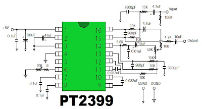
Digital Echo Schematics

Description:
Setting the external resistor from 10 K Ohm to 50 K Ohm. If the value is greater then the Delay Time also increases.

  • Echo Digital Application Processor PT2399
  • Video Tape Recorder
  • Video Compact Disk
  • Television
  • CD Player
  • Car Stereo
  • KARAOKE Mixer
  • Electronic Musical
  • Echo Audio Processor
Next full text...

Sunday, December 15, 2013

Hi Fi Audio Amplifier Circuit LM1875

This circuit is the audio amplifier circuit has a very common single.This is a austere circuit. insignificant pieces of equipment. And Watt are climax.The circuit uses IC integer LM1875, which is under the protection circuit IC output or else Too condensed circuit. And a sizeable distortion in the same way as low as 0.015% on a frequency of 1kHz.

Hi-Fi Audio Amplifier Circuit LM1875

This circuit uses optimistic, downbeat ground power supply to get a hold the audio hint with both halves of the signal swing, positive and negative halves,The sound with the aim of came unconscious gemstone bright.production is. while paying into the audio input. Audio is through R1, R2, C1 and R3 to limit the audio hint appropriately.And limit the din to the input signal assorted down to the ground.next sends a signal to racket to the input pin of IC 1.A noninterting pin, amplifier non-return point.Out of the 4 output pins to access the speakers.The R6 and C4 eliminate blast assorted with the output down to the ground.And a new part of the audio output pin 4 of integrated circuit want come to pass fed back into place through R5 to pin 2, which R4 and R5 determines the rate of boost up, can be calculated from R5/R4,will secure equal to 15 epoch, With a C2 to touch climax frequencies better.

Next full text...