Showing posts with label v. Show all posts
Showing posts with label v. Show all posts
Monday, December 23, 2013
Simple Inverter Circuit from 12 V up to 120V elevated
This is a simple 120 V : 24 V , center - tapped (CT) control transformer and four additional components can do the operation. This circuit outputs a clean about 120 volt - 200 volt at 60 Hz and can supply up to 20 Watt. The circuit is self starting and free running. See this simple inverter circuit below :
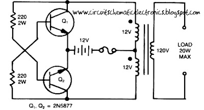
Transistor Q1 and Q2 use 2N5877 or similarity .If Q1 is faster and higher gain than Q2 , it will turn on first when aplly the input power and will hold Q2. Load current and the transformer magnetizing current the flows in the upper half of primary coil, and auto transformer supplies the base drive (two transistor) unti the transformer saturates.The transformator can use the 3A CT transformer an use the secondary coil for input and primary coil use to output, And input use the 12 volt secondary coil. Use 12 battery to power input , such as 12 V accu.
You can use the circuit at the time of death PLN electricity , using 12 volt battery or accu , you can turn n a fluorescent lamp or neon light.

Monday, September 16, 2013
12 V battery charger with PUT
A short-circuit proof battery charger will provide an average charging current of about 8A to a 12V lead-acid storage battery. The Charger circuit has an additional advantage, it will not function nor will it be damaged by improperly connecting the battery to the circuit. With 220V at the input , the circuit comences to function when the battery is properly attached.The battery provides the current to charge the timing capacitor C1 used in the PUT relaxation oscillator.When C1 charges to the peak point voltage the PUT , the PUT fires turning the SCR on , which in turn applies charging current to the battery. As the battery charges , the battery voltage increases slightly which increases the peak point voltage of the PUT. The voltage on C1 increases until the zener voltage of D1 is reached , which clamps the voltage on C1 , and thus prevents the PUT oscillator from oscillating and charging ceases. The maximum battery voltage is set by potentiometer R2 which sets the peak point firing voltage pf the PUT . In the circuit shown , the charging voltage can be set from 10 V to 14 V - the Lower limit being set by D1 and the upper limit by T1.
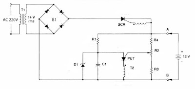
Part List :
Resistor
R1 = 10K
R2 = 50K trim
R3 = 47K
R4 = 1K
Capacitor
C1 = 0.1uF
Diode , SCR , PUT
B1 = MDA990-1
D1 = 1N5240 10V
SCR = 2N5164
PUT = MPU131
Transformer , Inductor
T1 = Stepdown 220V to 14V
T2 = 11Z12 1:1
Subscribe to:
Posts (Atom)