Showing posts with label from. Show all posts
Showing posts with label from. Show all posts
Monday, December 23, 2013
Simple Inverter Circuit from 12 V up to 120V elevated
This is a simple 120 V : 24 V , center - tapped (CT) control transformer and four additional components can do the operation. This circuit outputs a clean about 120 volt - 200 volt at 60 Hz and can supply up to 20 Watt. The circuit is self starting and free running. See this simple inverter circuit below :
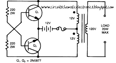
Transistor Q1 and Q2 use 2N5877 or similarity .If Q1 is faster and higher gain than Q2 , it will turn on first when aplly the input power and will hold Q2. Load current and the transformer magnetizing current the flows in the upper half of primary coil, and auto transformer supplies the base drive (two transistor) unti the transformer saturates.The transformator can use the 3A CT transformer an use the secondary coil for input and primary coil use to output, And input use the 12 volt secondary coil. Use 12 battery to power input , such as 12 V accu.
You can use the circuit at the time of death PLN electricity , using 12 volt battery or accu , you can turn n a fluorescent lamp or neon light.

Friday, November 8, 2013
Make a series letters from the LED
Make a series letters from the LED , Things to consider before making the sign of the LED array,
1) Use LED nodes.
2) Paint the top of the PCB with a dark color (black).
3) Note the LED specifications. In this experiment use a 5mm diameter LED nodes
that emit red, specification voltage of 3 volts.
The assembly of LED:
1) One letter composed at most 5 columns and 7 rows.
2) One column mostly composed by 6 LEDs are arranged series.
3) Then the fifth column are connected in parallel.
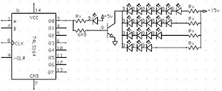
Here is one letter LED scheme.
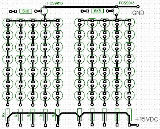
Medium picture below is the lay out of the 2-letter nameplate. To make the sign 8 letter, copied from a second stay this letter.
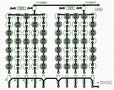
Example of LED on the letters A and B:
Next full text...
1) Use LED nodes.
2) Paint the top of the PCB with a dark color (black).
3) Note the LED specifications. In this experiment use a 5mm diameter LED nodes
that emit red, specification voltage of 3 volts.
The assembly of LED:
1) One letter composed at most 5 columns and 7 rows.
2) One column mostly composed by 6 LEDs are arranged series.
3) Then the fifth column are connected in parallel.
4) Each column given the constraints, Rx, which amount depends on the number of LEDs in one column and depends also on the type of LED (in this experiment that used LED 5mm in diameter, clear with red light beam).
5) In a column consisting of 6 LEDs, Rx = 330 ohm, 5 LEDs, Rx = 560 Ohms, 4 LEDs, Rx = 680 Ohms Remember, this provision applies to 5 mm LED red light beam nodes.
6) Every letter was given FCS9013 transistor amplifier. Here is one letter LED scheme.
Medium picture below is the lay out of the 2-letter nameplate. To make the sign 8 letter, copied from a second stay this letter.
Example of LED on the letters A and B:
Value Rx in the first and the fifth column (letter A) of 560 ohms, because it consists of 5 LEDs are arranged series. Rx in the second column, third, and fourth, amounting to 680 ohms because it consists of two LEDs.
Rx first column letter B, 330 ohms. Rx second column, third, fourth, and fifth at 680 ohms.Friday, October 18, 2013
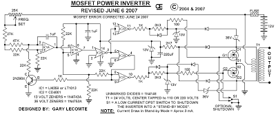
500W Mos Fet Power Inverter from 12V to 110V 220V
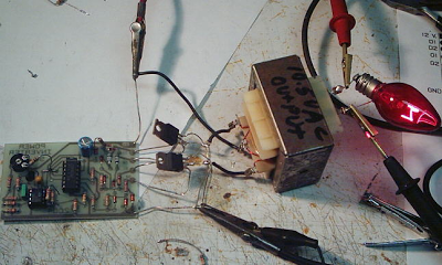
This circuit will provide a very stable "Square Wave" Output Voltage. Frequency of operation is determined by a pot and is normally set to 60 Hz. Various "off the shelf" transformers can be used. Or Custom wind your own FOR BEST RESULTS. Additional MosFets can be paralleled for higher power. It is recommended to Have a "Fuse" in the Power Line and to always have a "Load connected", while power is being applied. The Fuse should be rated at 32 volts and should be approximately 10 Amps per 100 watts of output. The Power leads must be heavy enough wire to handle this High Current Draw!
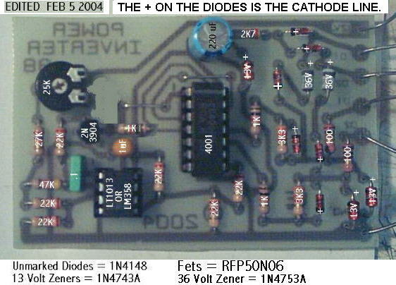
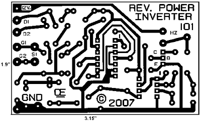
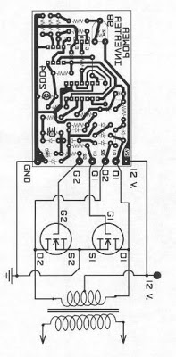
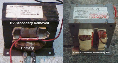
Appropriate Heat Sinks Should be used on the RFP50N06 Fets. These Fets are rated at 50 Amps and 60 Volts. ** Other types of Mosfets can be substituted if you wish. The LT1013 offers better drive that the LM358, but its your choice. The Power transformer must be capable of handling the chosen wattage output. Also, Appropriate Heat Sinks are Necessary on the Mos-Fets. Using a rebuilt Microwave transformer as shown below, it should handle about 500 watts Maximum. It requires about 18 turn Center-Tapped on the primary. To handle 500 watts would require using a 5 AWG wire. Pretty Heavy Stuff, but so is the current draw at that power.
Subscribe to:
Posts (Atom)