Showing posts with label to. Show all posts
Showing posts with label to. Show all posts
Sunday, January 12, 2014
Inverter 12V to 115V with 25 W power output
Low power inverter schematic are only use 9 components , one of which IC 556 , TIP120 NPN Darlington transistor.And turns 10 to 16 Vdc into 60 HZ, output 115 V square-wave power to operate ac equipment up to 25 W. In the circuit first ic originally hires as a timer chip m for stabilizatiom oscilator with components R1 and C1 setting frequency oscilator. Then the two transistor driver, drive the transformer push-pull fashion, When one transistor is biased on , the other circuit cut-off . The transformer is a 120V/18Vct unit that is connected backwards, so that it steps the voltage up rather than down. Oscilator circuit operates from about 4 to 16 V for stable output.
Part List :
R1 = 1K
R2 = 12K
R3 = 1K
R4 = 1/4W
C1 = 1uF
IC = 556
Q1 = TIP120
Q2 = TIP120
T1 = 120V 18VCT

Thursday, December 26, 2013
00 To 99 Minute Timer Using PIC16F628A Microcontroller
his might be a good practice project for beginners who just started learning embedded electronics. It is about making a very basic programmable digital timer using a PIC16F628A microcontroller. The timer duration can be set from 0-99 minutes.
As I mentioned earlier, the microcontroller used in this project is PIC16F628A running at 4.0 MHz clock using an external crystal. An HD44780 based 16×2 character LCD is the main display unit of the project where you can watch and set the timer duration using tact switch inputs. There are three tact switches connected to RB0 (Start/Stop), RB1 (Unit), and RB2 (Ten) pins. You can select the timer interval from 0-99 min using Unit and Ten minute switches. The Start/Stop switch is for toggling the timer ON and OFF. When the timer gets ON, a logic high signal appears on the RA3 pin, which can be used to switch on a Relay. The circuit diagram of this project is described below.

When the device is powered ON, the microcontroller initializes the LCD display and shows the following message. The timer is initially OFF and so does the LED or relay, whichever is connected to RA3 pin. You can set time duration between 00-99 min (in step of 1 min) using the Unit and Ten tact switches. Each switch press will increment the corresponding time digit.
When the desired time is set, press the Start/Stop switch to turn ON the timer. The RA3 pin goes high (LED glows) and the count down begins. When the timer is ON, the remaining time is also shown on the LCD screen. When the time elapsed, the timer stops and the LED turns OFF. You can interrupt and stop the timer at anytime by pressing the Start/Stop switch once more. The firmware for PIC is developed using mikroC Pro for PIC compiler. The use of Timers are avoided for simplicity. The time delays are created using the Delay_ms() function of mikroC, which seems to give reasonably accurate timing delays.
Download Mikroc Source Code And HEX File

As I mentioned earlier, the microcontroller used in this project is PIC16F628A running at 4.0 MHz clock using an external crystal. An HD44780 based 16×2 character LCD is the main display unit of the project where you can watch and set the timer duration using tact switch inputs. There are three tact switches connected to RB0 (Start/Stop), RB1 (Unit), and RB2 (Ten) pins. You can select the timer interval from 0-99 min using Unit and Ten minute switches. The Start/Stop switch is for toggling the timer ON and OFF. When the timer gets ON, a logic high signal appears on the RA3 pin, which can be used to switch on a Relay. The circuit diagram of this project is described below.
When the desired time is set, press the Start/Stop switch to turn ON the timer. The RA3 pin goes high (LED glows) and the count down begins. When the timer is ON, the remaining time is also shown on the LCD screen. When the time elapsed, the timer stops and the LED turns OFF. You can interrupt and stop the timer at anytime by pressing the Start/Stop switch once more. The firmware for PIC is developed using mikroC Pro for PIC compiler. The use of Timers are avoided for simplicity. The time delays are created using the Delay_ms() function of mikroC, which seems to give reasonably accurate timing delays.
Download Mikroc Source Code And HEX File
Monday, December 23, 2013
Simple Inverter Circuit from 12 V up to 120V elevated
This is a simple 120 V : 24 V , center - tapped (CT) control transformer and four additional components can do the operation. This circuit outputs a clean about 120 volt - 200 volt at 60 Hz and can supply up to 20 Watt. The circuit is self starting and free running. See this simple inverter circuit below :

Transistor Q1 and Q2 use 2N5877 or similarity .If Q1 is faster and higher gain than Q2 , it will turn on first when aplly the input power and will hold Q2. Load current and the transformer magnetizing current the flows in the upper half of primary coil, and auto transformer supplies the base drive (two transistor) unti the transformer saturates.The transformator can use the 3A CT transformer an use the secondary coil for input and primary coil use to output, And input use the 12 volt secondary coil. Use 12 battery to power input , such as 12 V accu.
You can use the circuit at the time of death PLN electricity , using 12 volt battery or accu , you can turn n a fluorescent lamp or neon light.
Sunday, December 15, 2013
Lead achid battery charger up to 3 battery
See battery charger circuit below :
 | |
| This is charger battery circuit |
Above circuit furnishes an initial voltage of 2.5 Volt per Cell at 25 degree celcius to rapidly charge a battery . the charging current decreases as the battery cahrges , and when the current drop 180 mA , the charging circuit reduces the output voltage to 2.35 V per cell, leaving the battery in a fully charged state.
Thursday, November 21, 2013
Frequency to Voltage Converter
Overview of IC LM2917 as Frequency to Voltage Converter
 Very easy to apply in measuring the output frequency with the formulation of single-chip Frequency to Voltage Converter VOUT = FIN x VCC x R1 x C1. Then the single-chip LM2917 Frequency to Voltage Converter This configuration requires only the RC only in frequncy doublings. And has an internal zener regulator to aimlessly accuracy and stability in frequency-to-voltage conversion process.
Next full text...
IC LM2917 IC chip is designed specifically as a Frequency to Voltage Converter or Frequency to Voltage converter. In its use to applications Frequency to Voltage Converter IC LM2917 requires few external components.
There are several examples of applications of Frequency to Voltage Converter IC LM2917 is supplied in the LM2917 IC datahseet. In this article series Frequency to Voltage Converter IC also taken from the LM2917 datasheet. The advantages of single chip LM2917 Frequency to Voltage Converter is able to provide instantaneous volt output o at time of frequency change 0 Hz.
There are several examples of applications of Frequency to Voltage Converter IC LM2917 is supplied in the LM2917 IC datahseet. In this article series Frequency to Voltage Converter IC also taken from the LM2917 datasheet. The advantages of single chip LM2917 Frequency to Voltage Converter is able to provide instantaneous volt output o at time of frequency change 0 Hz.
Very easy to apply in measuring the output frequency with the formulation of single-chip Frequency to Voltage Converter VOUT = FIN x VCC x R1 x C1. Then the single-chip LM2917 Frequency to Voltage Converter This configuration requires only the RC only in frequncy doublings. And has an internal zener regulator to aimlessly accuracy and stability in frequency-to-voltage conversion process. |
| Frequency to Voltage Converter |
Feature-owned single-chip LM2917 Frequency to Voltage Converter
- Reference to ground directly with variable reluctance
- Op Amp / Comparator with transistor output
- 50 mA maximum output currents for application directly to the load
- Frequency doubling untul low ripel
- Buid in zener
- Linear output ± 0.3%
Application single chip LM2917 Frequency to Voltage Converter
- Frequency to Voltage Converter
- Rotation speed sensor applications
- Speedometer
- Tachometer
- Cruise Control
- Cluth Control
And other application associated with the measurement of rotation speed or frequency measurements.
Monday, November 18, 2013
DC DC Converter 12V to 24V
This simple circuit is a DC-DC converter that converting up 12V source to a 24V. It can be used to run radios, small lights, relays, horns and other 24V accessories from a 12V vehicle with a maximum draw of about 800mA.
This DC-DC Converter can be used to charge one 12V battery from another, or step up the voltage just enough to provide necessary overhead for a 12V linear regulator. Using one op-amp as a squarewave oscillator to ring an inductor and another op-amp in a feedback loop, it wont drift around under varying loads, providing a stable 24V source for many applications. With a wide adjustment in output this circuit has many uses.
Parts List
R1-R4,R7-R8 100K 1/4W Resistor
R5 470 Ohm 1/2W Resistor
R6 10K Linear Pot
C1 0.01uF Mylar Capacitor
C2 0.1uF Ceramic Disc Capacitor
C3 470uF 63V Electrolytic Capacitor
D1 1N4004 Rectifier Diode
D2 BY229-400 Fast Recovery Diode See Notes
Q1 BC337 NPN Power Transistor
U1 LM358 Dual Op Amp IC
L1 See Notes
MISC Board, Wire, Socket For U1, Case, Knob For R6, Heatsink for Q1
DC- DC Converter Notes
1. R6 sets the output voltage. This can be calculated by Vout = 12 x (R8/(R8+R7)) x (R6B/R6A).
2. L1 is made by winding 60 turns of 0.63MM magnet wire on a toroidial core measuring 15MM (OD) by 8MM (ID) by 6MM (H).
3. D2 can be any fast recovery diode rated at greater then 100V at 5A. It is very important that the diode be fast recovery and not a standard rectifier. 4. Q1 will need a heatsink.
12V to 30V DC to DC Converter Schematic
12V to +/- 30V DC to DC Converter Circuit Diagram

This is a DC to DC converter for car power amplifier. 12V input generates +30V and -30V output for preamp or power amplifiers. Circuit uses SG3525 IC, Mosfets and switching power supply.
Thursday, November 7, 2013
6V to 220V inverter schematic
Circuit schematic above is one of the voltage inverter circuit, starting from 6-Volt input on the DC current into 220-volt AC output. For maximum output power up to 30W only, and is also very small voltage current. Input voltage plus the entrance on the transistor Q2 to provide the voltage at the collector and then go on Circumference transformer L1 and enter the base. Emitter will be merged ddengan voltage supplied L2 min. And LED1 is useful as an indicator of whether or not an inverter works especially on the transistor Q2.

Part List :
R1 = 1K R
R2 = 220R
C1 = 10nF
C2 = 100nF
C3 = 47nF
C4 = 0,22uF 400V
Q1 = 2N5551
Q2 = C5198
LED1 use Green Led
Transformer instruction :

The above is figure from a place plastic for copper wire wrapped around, you can also use the marks that have been unused transformer. For the above number are :
1 : Place for copper wire wrapped,with a diameter of 12mm x 10mm.
2 : Hole to place an iron or ferrite rod , with diameter 10mm. 
3 : Copper wire that has been rolled.
4 : Ferrite or iron rods which are mounted on the hole.
To coil L1 as much as 70 times, L2 200 times, And L3 as much as 1000 times.
L1 wire diameter 1mm
L2 wire diameter 0.8mm
L3 wire diameter 0.4 mm
4 : Ferrite or iron rods which are mounted on the hole.
To coil L1 as much as 70 times, L2 200 times, And L3 as much as 1000 times.
L1 wire diameter 1mm
L2 wire diameter 0.8mm
L3 wire diameter 0.4 mm
Friday, November 1, 2013
555 Timer for DC to DC Converter Circuit
 |
| 555 Timer for DC to DC Converter |
This circuit is called DC TO DC converter circuit.Which increase the voltage circuit.There can be customized to change the output values. When the power supply input to IC1 is the output pin 3 at a frequency of 1 kHz.The frequency is Q1 and Q2, which will continue to use push pool work interchangeably.If this is the positive output signal Q1 Q2 will run the delete function this reason, C2 and C3 capacitors are half-wave alternating.When to use. Voltage from C2 to C3 is discharged out to the input voltage over almost two times less than 2 times due to the loss of diodes D1-D3.
Sunday, October 27, 2013
6 to 12 Volt Power Supply Inverter
This inverter circuit can provide up to 800mA of 12V power from a 6V supply. For example, you could run 12V car accessories in a 6V (British?) car.
The circuit is simple, about 75% efficient and quite useful. By changing just a few components, you can also modify it for different voltages.

Part List:
R1, R4 2.2K 1/4W Resistor
R2, R3 4.7K 1/4W Resistor
R5 1K 1/4W Resistor
R6 1.5K 1/4W Resistor
R7 33K 1/4W Resistor
R8 10K 1/4W Resistor
C1,C2 0.1uF Ceramic Disc Capacitor
C3 470uF 25V Electrolytic Capcitor
D1 1N914 Diode
D2 1N4004 Diode
D3 12V 400mW Zener Diode
Q1, Q2, Q4 BC547 NPN Transistor
Q3 BD679 NPN Transistor
L1 See Notes
MISC Heatsink For Q3, Binding Posts (For Input/Output), Wire, Board
Next full text...
The circuit is simple, about 75% efficient and quite useful. By changing just a few components, you can also modify it for different voltages.
Part List:
R1, R4 2.2K 1/4W Resistor
R2, R3 4.7K 1/4W Resistor
R5 1K 1/4W Resistor
R6 1.5K 1/4W Resistor
R7 33K 1/4W Resistor
R8 10K 1/4W Resistor
C1,C2 0.1uF Ceramic Disc Capacitor
C3 470uF 25V Electrolytic Capcitor
D1 1N914 Diode
D2 1N4004 Diode
D3 12V 400mW Zener Diode
Q1, Q2, Q4 BC547 NPN Transistor
Q3 BD679 NPN Transistor
L1 See Notes
MISC Heatsink For Q3, Binding Posts (For Input/Output), Wire, Board
source:LINK
Friday, October 18, 2013
500W Mos Fet Power Inverter from 12V to 110V 220V

This circuit will provide a very stable "Square Wave" Output Voltage. Frequency of operation is determined by a pot and is normally set to 60 Hz. Various "off the shelf" transformers can be used. Or Custom wind your own FOR BEST RESULTS. Additional MosFets can be paralleled for higher power. It is recommended to Have a "Fuse" in the Power Line and to always have a "Load connected", while power is being applied. The Fuse should be rated at 32 volts and should be approximately 10 Amps per 100 watts of output. The Power leads must be heavy enough wire to handle this High Current Draw!

Appropriate Heat Sinks Should be used on the RFP50N06 Fets. These Fets are rated at 50 Amps and 60 Volts. ** Other types of Mosfets can be substituted if you wish. The LT1013 offers better drive that the LM358, but its your choice. The Power transformer must be capable of handling the chosen wattage output. Also, Appropriate Heat Sinks are Necessary on the Mos-Fets. Using a rebuilt Microwave transformer as shown below, it should handle about 500 watts Maximum. It requires about 18 turn Center-Tapped on the primary. To handle 500 watts would require using a 5 AWG wire. Pretty Heavy Stuff, but so is the current draw at that power.


Tuesday, October 15, 2013
TA7210P Not only used to power amplifier it can to be companion
To improve the quality of the amplifier circuit above in addition to other power amplifiers , can also be as an additional reinforcement such as a master LA4145 BBE sound, audio processor , etc. For TA7210P ic can be used on the audio processor and power amplifiers , power amplifier refer to the spesifications below .
Part List :
R = 100K x 3 , 15R , 1R5 , 100R , 0,5R.
C = 10u , 220u , 100p , 150p , 100u x2 ,4u7 , 6n8 , 1000u , 100n
IC = TA7210P , TA7268P
Technical information :
Max. V = 40 Volt Dc
Min. V = 20 Volt Dc
P. Out = 22 Watt mono
R L = 4 Ohm

Wednesday, October 9, 2013
1 3V DC to 12 2V DC Regulator Power Supply
Power supply circuit to generate output below were variations between 1.3V DC to 12.2V DC with 1A current.
In addition, the power supply circuit is also equipped with over-current protection or shield against belebih flow. Power supply circuit is very simple, but the quality is quite good, made her basiskan regulator IC LM723 is a pretty legendary.
In addition, the power supply circuit is also equipped with over-current protection or shield against belebih flow. Power supply circuit is very simple, but the quality is quite good, made her basiskan regulator IC LM723 is a pretty legendary.

Description:
R2 to set the output voltage. The maximum current is determined by R3, over-current protection circuit inside the LM723 to detect the voltage on R3, if it reaches 0.65 V, the voltage output will be off her. So the current through R3 can not exceed 0.65 / R3 although output short-circuit in his.
C3 and C4 are ceramic capacitors, as much as possible directly soldered to the PCB, this is because the LM723 is prone to oscillation that is not cool.
LM723 works with 9.5V input voltage to 40 V DC and the LM723 can generate its own current of 150mA when the output voltage is not more than 6-7V under input voltage.
Specifications:
Output (value estimated):
Vmin = (R4 + R5) / (R5 * 1.3)
Vmax = (7.15 / R5) * (R4 + R5)
Imax = 0.65/R3
Max. Power on R3: 0.42/R3
Min. DC Input Voltage (pin 12 to pin 7): Vmax + 5
Component List:
B1 40V/2.5A
C1 2200uF (3300uF even better)
C2 4.7uF
C3 100nF
C4 1NF
C5 330nF
C6 100uF
Green LED D1
D2 1N4003
F1 0.2A F
F2 2A M
IC1 LM723 (in a DIL14 plastic package)
R1 1k
R2 Pot. 5k
R3 0.56R/2W
R4 3.3k
R5 4.7k
S1 250V/1A
T1 2N3055 on a heatsink 5K / W
TR1 220V/17V/1.5
source [link]
12VDC to 220V AC 500W Inverter Circuit
Circuit Inverter 500 Watt 12VDC to 220VAC is made using a transistor.
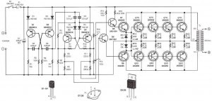
The basiccally of the circuit Inverter 12VDC to 220VAC 500 Watt This is a configuration of 2 pieces of transistors Q1 and Q2 which form a series of Flip-Flop. The output of the flip-flop Q1 and Q2 in the circuit Inverter 12VDC to 220VAC 500 Watt is then broken down for each pulse to complement each other using a series compiled by Q3 and Q4. Output which complement each other is then given to the driver transistors Q5 and Q6 form the transistor 2SC1061. Series Inverter Power Inverter from 12VDC to 220VAC 500 Watt This is a series of parallel transistors Q7 and Q8 are prepared and Q7x and Q8x the form of power with a type 2N3055 transistor 10 pieces. drawing a complete range of circuit Inverter 12VDC to 220VAC 500 Watts can be seen as follows.
Sunday, October 6, 2013
6 to 12 Volt Converter
Below its a converter circuit voltage from 6 Volt to 12 Volt DC.
 |
| 6 Volt to 12 Volt DC |
Part List :
R1, R4 2 .2K 1/4W Resistor
R2, R3 4.7K 1/4W Resistor
R5 1K 1/4W Resistor
R6 1.5K 1/4W Resistor
R7 33K 1/4W Resistor
R8 10K 1/4W Resistor
C1,C2 0.1uF Ceramic Disc Capacitor
C3 470uF 25V Electrolytic Capcitor
D1 1N914 Diode
D2 1N4004 Diode
D3 12V 400mW Zener Diode
Q1, Q2, Q4 BC547 NPN Transistor
Q3 BD679 NPN Transistor
L1 See Notes
Notes
1. L1 is a custom inductor wound with about 80 turns of 0.5mm magnet wire around a toroidal core with a 40mm outside diameter.
2. Different values of D3 can be used to get different output voltages from about 0.6V to around 30V. Note that at higher voltages the circuit might not perform as well and may not produce as much current. You may also need to use a larger C3 for higher voltages and/or higher currents.
3. You can use a larger value for C3 to provide better filtering.
4. The circuit will require about 2A from the 6V supply to provide the full 800mA at 12V.
Saturday, October 5, 2013
DC to AC Inverter with IC CD4047
This DC to AC inverter circuit work based on unstable multi vibrator does. In this circuit, IC CD4047 is chosen as a heart of unstable multivibrator, because this IC type gives a complementary output that has opposite phase to another ( pin 10 and 11 as seen in Figure 1), and has 50 % duty cycle that satisfy to generate a pulse for inverter.
DC to AC Inverter with IC CD4047 Circuit Diagram

DC to AC Inverter with IC CD4047 Circuit Diagram
Wednesday, October 2, 2013
12V to 220V Inverter Schematics
12V to 220V Inverter Circuit Diagrams, Even though today’s electrical appliances are increasingly often self-powered, especially the portable ones you carry around when camping or holidaying in summer, you do still sometimes need a source of 230 V AC - and while we’re about it, why not at a frequency close to that of the mains? As long as the power required from such a source remains relatively low - here we’ve chosen 30 VA - it’s very easy to build an inverter with simple, cheap components that many electronics hobbyists may even already have 12V to 220V Inverter.
 |
| 12V to 220V Inverter Circuit Diagrams |
Though it is possible to build a more powerful circuit, the complexity caused by the very heavy currents to be handled on the low-voltage side leads to circuits that would be out of place in this summer issue. Let’s not forget, for example, that just to get a meager 1 amp at 230 VAC, the battery primary side would have to handle more than 20 ADC!. The circuit diagram of 12V to 220V Inverter Schematics our project is easy to follow. A classic 555 timer chip, identified as IC1, is configured as an astable multivibrator at a frequency close to 100 Hz, which can be adjusted accurately by means of potentiometer P1.
As the mark/space ratio (duty factor) of the 555 output is a long way from being 1:1 (50%), it is used to drive a D-type flip-flop produced using a CMOS type 4013 IC. This produces perfect complementary square-wave signals (i.e. in antiphase) on its Q and Q outputs suitable for driving the output power transistors. As the output 12V to 220V Inverter current available from the CMOS 4013 is very small, Darlington power transistors are used to arrive at the necessary output current. We have chosen MJ3001s from the now defunct Motorola (only as a semi-conductor manufacturer, of course!) which are cheap and readily available, but any equivalent power Darlington could be used.
These drive a 230 V to 2 × 9 V center-tapped transformer used ‘backwards’ to produce the 230 V output. The presence of the 230 VAC voltage is indicated by a neon light, while a VDR (voltage dependent resistor) type S10K250 or S07K250 clips off the spikes and surges that may appear at the transistor switching points. The output signal this circuit produces is approximately a square wave; only approximately, since it is somewhat distorted by passing through the transformer. Fortunately, it is suitable for the majority of electrical devices it is capable of supplying, whether they be light bulbs, small motors, or power supplies for electronic devices.
PCB layout:

COMPONENTS LIST
Resistors
R1 = 18k?
R2 = 3k3
R3 = 1k
R4,R5 = 1k?5
R6 = VDR S10K250 (or S07K250)
P1 = 100 k potentiometer
Capacitors
C1 = 330nF
C2 = 1000 µF 25V
Semiconductor
T1,T2 = MJ3001
IC1 = 555
IC2 = 4013
Miscellaneous
LA1 = neon light 230 V
F1 = fuse, 5A
TR1 = mains transformer, 2x9V 40VA (see text)
4 solder pins
Note that, even though the circuit is intended and designed for powering by a car battery, i.e. from 12 V, the transformer is specified with a 9 V primary. But at full power you need to allow for a voltage drop of around 3 V between the collector and emitter of the power transistors. This relatively high saturation voltage is in fact a ‘shortcoming’ common to all devices in Darlington configuration, which actually consists of two transistors in one case. We’re suggesting a PCB design to make it easy to construct this project; as the component overlay shows, the PCB only carries the low-power, low-voltage components.
The Darlington transistors should be fitted onto a finned anodized aluminum heat-sink using the standard insulating accessories of mica washers and shouldered washers, as their collectors are connected to the metal cans and would otherwise be short-circuited. An output power of 30 VA implies a current consumption of the order of 3 A from the 12 V battery at the ‘primary side’. So the wires connecting the collectors of the MJ3001s [1] T1 and T2 to the transformer primary, the emitters of T1 and T2 to the battery negative terminal, and the battery positive terminal to the transformer primary will need to have a minimum cross-sectional area of 2 mm2 so as to minimize voltage drop.
The transformer can be any 230 V to 2 × 9 V type, with an E/I iron core or toroidal, rated at around 40 VA. Properly constructed on the board shown here, the circuit should work at once, the only adjustment being to set the output to a frequency of 50 Hz with P1. You should keep in minds that the frequency stability of the 555 is fairly poor by today’s standards, so you shouldn’t rely on it to drive your radio-alarm correctly – but is such a device very useful or indeed desirable to have on holiday anyway? Watch out too for the fact that the output voltage of this inverter is just as dangerous as the mains from your domestic power sockets.
So you need to apply just the same safety rules! Also, the project should be enclosed in a sturdy ABS or diecast so no parts can be touched while in operation. The circuit should not be too difficult to adapt to other mains voltages or frequencies, for example 110 V, 115 V or 127 V, 60 Hz. The AC voltage requires a transformer with a different primary voltage (which here becomes the secondary), and the frequency, some adjusting of P1 and possibly minor changes to the values of timing components R1 and C1 on the 555.
B. Broussas
Source : Link
Another interesting related Circuit : DC 12V to 24V Contverter, 5000W PWM inverter, and other Inverter / Converter Circuit.
Another interesting related Circuit : DC 12V to 24V Contverter, 5000W PWM inverter, and other Inverter / Converter Circuit.
Wednesday, September 25, 2013
The Reasons Why you should add a DVD Player to your Auto Sound System
When you are in the process of selecting your next auto sound system you might want to check out the systems that include other entertainment features such as games and DVD players. This may sound a little simplistic to some but if youve ever driven cross-country with children, you know what I mean when I say it is worth the investment to have one installed and have it installed correctly.
Many people will debate the wisdom of these devices and I will tell you quite frankly that I feel 100% that this is much safer than trying to deal with disgruntled children in the back that are literally fighting for your attention. If you want to talk about a distraction, I can think of few distractions that will top that while driving in holiday packed roads and less than favorable weather conditions. The truth of the matter is that anything that keeps the kiddies quiet for two hours at a pop has my vote for gadget or gizmo of the year.
I seriously recommend having a system installed however as this will limit not only the distraction to the driver but also the exposure of the lights and sounds to the driver as well. If you have a game system in stalled along with a DVD player and headphones to go with both I am sure you will find that you are driving along listening blissfully to your mom music as the kids in the back take turns playing games and watching DVDs. In fact, the most serious refereeing you are likely to need is over whose turn it is and how long that will last.
Now, I feel that it is very important to point out that this is not the only benefit to having an entertainment system installed for children that are traveling with you. Another very real benefit is the fact that you will also find that you are hearing less and less of the usual "are we there yet" and other generally disgruntled forms of questions from the backset. I also love the fact that the kids can often fall asleep to a DVD that they have seen a few dozen times which will bring a few more minutes of blissful silence as they snooze.
Another unexpected benefit I have found with my children and a DVD incorporated into an auto sound system is that my children are asking less often to stop for potty breaks. I always assumed that some of the frequent bathroom stops were boredom related and now Im fairly certain that my assumptions were correct. Another great thing that mommy does in order to keep things going smoothly is purchase a new DVD immediately prior to taking a long road trip. In addition to a new DVD that the little ones will not yet be tired of, I pull out some DVDs that might have been forgotten recently and not watched quite as often. This keeps the children very happy and quiet while mommy is able to concentrate on the road ahead and keeping everyone happy and safe while traveling.
Just remember that you should never rely on the scenery or the thrill of traveling in order to keep little ones happy and occupied on long trips. Endless questions and chatter are to be expected in order to alleviate boredom. In order to avoid these types of situations youll need more than happy music playing on the radio and really, how many times can you listen to "The Itsy Bitsy Spider" during a 12 hour road trip? Do yourself a favor when selection a really great auto sound system and make the necessary investment to add a really nice DVD player into the mix. Believe me I am the queen of cheap when it comes to trying to save money and will swear up and down that if you have children, this is one investment that is worth its weight in gold.
Monday, September 23, 2013
Frequency to Voltage Converter
Overview of IC LM2917 as Frequency to Voltage Converter
Very easy to apply in measuring the output frequency with the formulation of single-chip Frequency to Voltage Converter VOUT = FIN x VCC x R1 x C1. Then the single-chip LM2917 Frequency to Voltage Converter This configuration requires only the RC only in frequncy doublings. And has an internal zener regulator to aimlessly accuracy and stability in frequency-to-voltage conversion process.
Next full text...
IC LM2917 IC chip is designed specifically as a Frequency to Voltage Converter or Frequency to Voltage converter. In its use to applications Frequency to Voltage Converter IC LM2917 requires few external components.
There are several examples of applications of Frequency to Voltage Converter IC LM2917 is supplied in the LM2917 IC datahseet. In this article series Frequency to Voltage Converter IC also taken from the LM2917 datasheet. The advantages of single chip LM2917 Frequency to Voltage Converter is able to provide instantaneous volt output o at time of frequency change 0 Hz.
There are several examples of applications of Frequency to Voltage Converter IC LM2917 is supplied in the LM2917 IC datahseet. In this article series Frequency to Voltage Converter IC also taken from the LM2917 datasheet. The advantages of single chip LM2917 Frequency to Voltage Converter is able to provide instantaneous volt output o at time of frequency change 0 Hz.
Very easy to apply in measuring the output frequency with the formulation of single-chip Frequency to Voltage Converter VOUT = FIN x VCC x R1 x C1. Then the single-chip LM2917 Frequency to Voltage Converter This configuration requires only the RC only in frequncy doublings. And has an internal zener regulator to aimlessly accuracy and stability in frequency-to-voltage conversion process. |
| Frequency to Voltage Converter |
Feature-owned single-chip LM2917 Frequency to Voltage Converter
- Reference to ground directly with variable reluctance
- Op Amp / Comparator with transistor output
- 50 mA maximum output currents for application directly to the load
- Frequency doubling untul low ripel
- Buid in zener
- Linear output ± 0.3%
Application single chip LM2917 Frequency to Voltage Converter
- Frequency to Voltage Converter
- Rotation speed sensor applications
- Speedometer
- Tachometer
- Cruise Control
- Cluth Control
And other application associated with the measurement of rotation speed or frequency measurements.
Wednesday, September 11, 2013
How to Installation A Car Stereo
Car Stereo Installation Guide - Want to save some money? Ever wonder if you could do a car stereo installation yourself? Yes, you can do it yourself! Go ahead, spend that money on your hardware! Don’t spend it on labor. Besides, doing a car stereo installation yourself can be a very rewarding experience, not to mention you can learn a lot from it too. Nothing beats the feeling of seeing your “creation” in action, running smoothly and perfectly.

But be very careful, you really won’t want to damage your expensive hardware. Well, most car audio hardware are no-brainers to install, you’d find that most of the time the parts have specially shaped sockets and slots etc. and would only fit where it’s supposed to be installed. Still, it’s best to proceed methodically.
In a car stereo installation, you have to determine what kind of rig you’re going to put into your vehicle. If you’re a beginner, it’s best you do a car stereo installation if it’s just a simple system. You may want to leave the complicated stuff to the professionals, like installing delicate equipment like LCD panels, motorized parts etc. especially if it requires the creation of custom panels and such.
Head units are one of the easiest to do in a car stereo installation. Fortunately, most units follow the same size standards (DIN). In many cars, once the factory radio is removed the aftermarket radio will fit in the hole. In many other cars, a kit is needed if the factory hole is too big, or not deep enough. In some cases the dash has to be cut. Any car stereo store should have kits required for installation.
There are two types of mounting in a car stereo installation. ISO mounting is when the radio can be screwed to existing factory radio brackets, such as in most Japanese cars. Ring mounting is when an aftermarket radio comes with a metal ring that gets mounted to the factory radio hole or aftermarket kit via bendable tabs. In many cars, dash and trim rings have to be filed to enlarge the radio hole. Once the ring is installed, the radio slides in and is held by snaps. In most cases, special tools are required to remove the radio.
Speakers are very critical in a car stereo installation. No matter how expensive your speakers are, if they are not properly installed, the sound will not be up to par.
In a simple car stereo installation, you’ll probably be using speakers that fit into a factory location. Just make sure there are no gaps or holes. Sometimes building a wood or fiberglass baffle helps reduce holes and gives you much better sound. But always be careful when using power tools around speakers. Car stereo installation warranties usually dont cover holes in speakers.
For unconventional speaker locations, sometimes metal has to be cut. You might want to leave this to the professionals, tools like plasma cutters and pneumatics drills are required. But if you’re going to insist, a pair of metal snips (left and right cut) will do.
A car stereo installation has to put up with vibrations and other noise sources in its environment. Even though it is impossible to eliminate these completely, there are products that will greatly decrease the noise and rattling, particularly on non-luxury cars. Liners, sprays and adhesive strips and even carpeting applied onto the panels can make a world of difference.
Subscribe to:
Posts (Atom)