Showing posts with label supply. Show all posts
Showing posts with label supply. Show all posts
Friday, January 24, 2014
5 Volt Switching Regulator Power Supply
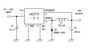
The switching regulator power supply used LM2575-5.0 on this schematic.
You can make the stable voltage by using the 3 terminal regulator like LM317. However, because the output electric current and the inputted electric current are the same approximately, the difference between the input electric power (The input voltage x The input electric current) and the output power (The output voltage x The output current) is consumed as the heat with the regulator. Because it is, the efficiency isn�t good.
You can make the stable voltage by using the 3 terminal regulator like LM317. However, because the output electric current and the inputted electric current are the same approximately, the difference between the input electric power (The input voltage x The input electric current) and the output power (The output voltage x The output current) is consumed as the heat with the regulator. Because it is, the efficiency isn�t good.
Data sheet for LM2575
SIMPLE SWITCHER 1A Step-Down Voltage Regulator
http://www.national.com/pf/LM/LM2575.htm

Monday, December 16, 2013
Protection of the Mosfet in flyback power supply
PKC-136 PEAK CLAMP CHARACTERISTICS VBR 160Vdc VDRM 700Vdc P 1.5W. See Circuits Diagram below :
Feature :
- Protection of the Mosfet in flyback power supply
- TRANSIL™ and blocking diode in a single package BENEFITS
- Accurate voltage clamping regardless load
- Reduced current loop
- Reduced EMI emission
- High integration
- Fast assembly
- Reduced losses in stand by mode
Next full text...
 |
| Protection of the Mosfet in flyback power supply |
- Protection of the Mosfet in flyback power supply
- TRANSIL™ and blocking diode in a single package BENEFITS
- Accurate voltage clamping regardless load
- Reduced current loop
- Reduced EMI emission
- High integration
- Fast assembly
- Reduced losses in stand by mode
Sunday, December 15, 2013
200W power amplifier complete power supply
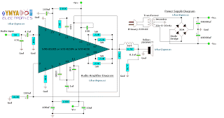
This 200W power amplifier circuit using IC STK 4050.
STK 4050 is a power amplifier module is very powerful, because the IC is already a module then only needed a little extra components to build a reliable 200W Power Amplifier. Here is a picture series of Power Amplifier ICs 200W use STK 4050 complete with its power supply:
STK 4050 is a power amplifier module is very powerful, because the IC is already a module then only needed a little extra components to build a reliable 200W Power Amplifier. Here is a picture series of Power Amplifier ICs 200W use STK 4050 complete with its power supply:
Tuesday, November 19, 2013
9V output switching power supply
By using the circuit you do not bother to roll up a transformer that is used to reduce voltage AC 220V to 7V ,9 V or 12V, etc. When using a large transformer we will find it hard to make transformator. by rolling hundreds or even thousands of times roll. But if you use this circuit a little just enough to roll trafo not to small, and its be relatively small.

R1________________________________680K
R2________________________________47K
R3________________________________100R
R4________________________________1K
R5________________________________1R
D1,D2,D3,D4,D7,D8,D9,D10__________1N4007
D5,D6_____________________________1N4148
C1________________________________2u2F 400V
C2________________________________2n2
C3________________________________47uF 25V
C4________________________________10n
C5________________________________470uF / 16V
Q1________________________________MJE13003
Q2________________________________S8050
This is construction of transformer. For the first toll 220 times , then after that wrap right on top of L2 , and L3 on L2.

Wednesday, November 13, 2013
Power Supply with regulator output use IC uA723
This circuit operating with IC uA723 and add amplified with transistor TIP31 or similiar transistor with TIP31 . Input voltage for circuit about 10 - 40 volt DC , formerly of AC voltage 220 volts or 110 volts , then lowered by the transformer voltage to 30 volts. And the supply output voltage from 1 volt to 35 volt DC you can adjust it on potentiometer R2.
See this circuit power supply below :

Output voltage transformer used 10 to 40 Volts . On resistor Rsc is the current limit set resistor. Its value is calculated as :
Rsc = 0.65 Volt For Example : If you need current output 2.0 A
Rsc = 0.65 / 2.0 = 0.32 Ohm So , you must use 0.32 Ohm to current output 2.0 A
Wednesday, November 6, 2013
Dual Power Supply
To build (or else design) solitary. here are a a small number of things one must come about sensitive with, such in the role of the routing of prohibitive current leads, but these are without difficulty accomplished. The earliest gadget to point out is a apt transformer. I hint toroidal transformers preferably than the traditional "EI" laminated types for the reason that they branch out a reduced amount of magnetic flux and are compliment, allowing them to subsist installed in vogue slimmer hand baggage.
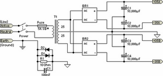
They resolve give various problems, such for instance elevated inrush current on switch on, which channel to facilitate lengthy blow fuses essential be used. representing the 60W amplifier, a nominal (filled load) supply of +/- 35V is vital, so a 25-0-25 secondary is ideal - however, escort Updates, lower. The circuit for the supply is given away below, and uses separate rectifiers, capacitors and fuses pro every one channel. merely the transformer is shared, so channel interactions are minimised. A single ±35V supply (i.e. using just a single association and put of filter capacitors) yearn for job immediately because well voguish the majority of luggage.
 |
| Dual Power Supply Circuit |
The 5A slow down-blow fuse given away is as it should be instead of a 300VA transformer, if a 120VA transformer is used, this be supposed to live compact to 2.5A (before 3A if 2.5A proves too awkward to search out). If you are even a minor fragment concerned roughly the fuse rating, phone the transformer manufacturer in support of the recommended charge for the transformer you force utilize. The correct fuse is life-threatening to ensure safety from electrical failure, which might conclusion participating in the equipment apt unsafe before causing a fire.
The capacitance used is not critical, but is somewhat dependent in the lead lones financial plan. I advocate 10,000uF capacitors, but they are fairly expensive so by the side of a pinch 4,700uF caps ought to be there fine - especially in the array revealed. what time unloaded (or else with individual light load), the voltage desire normally be somewhat privileged than 35 Volts. This is Ok, and ought to not cause distress to one amp. The voltage will fall in the same way as added current is drawn, and may well release less than 35V if a minute transformer (otherwise individual with unusually poor instruction) is used.
Two parts of this circuit are derogatory:
Mains wiring ought to exist cabled using official 240V rated insulated cable, and all terminations must be insulated to prevent unintended associate. The mains earth obligation be securely fixed firmly to the framework, afterward scraping away several paint or else other coating which might prevent dependable contact.
The centre-tap of the transformer and the ground points of apiece capacitor have to subsist connected to the major warning sign earth aspect via bodyguard duty copper wire, otherwise (rather) a copper motor vehicle-block. big currents emerge hip this part of the circuit, containing nasty current waveforms which are quite glad to invade your amplifier. The supply voltages duty live taken from the capacitors (not the join rectifiers) to prevent unwelcome hum and clatter.
after wiring the bridge rectifiers to the transformer, hook up exactly in the role of exposed to ensure with the purpose of move voltages (and currents) are dressed in time in favor of every one amp. If not, baffling hum signals may perhaps be present injected into the amps suggest path from bypass capacitors and the like. This is somewhat improbable but for giant caps are used on the amp board(s) - not recommended, by the way - but why take the expose?
association rectifiers must transpire the gigantic bolt-down 35A types (before something related) to ensure lowest feasible losses (these self-control not require an bonus heatsink - the carcass will normally be quite sufficient). The transformer primary voltage will apparently be real unwavering by the supply voltage during your area (i.e. 120, 220 or else 240) and be suited to the regional supply frequency. hint to facilitate all 50Hz transformers desire toil a moment ago fine by 60Hz, but more or less 60Hz diplomacy will overheat if used by the side of 50Hz.
The transformer ought to befall rated by a most minuscule of 120VA (Volt-Amps) on behalf of home-grown operation, but a 300VA transformer is recommended due to its exceptional government. available afar 300VA desire perform thumbs down informative determination, other than to dim the light such as it is crooked on. someplace it is potential, the pointer and power ground be supposed to be alive the same (this prevents the chance of an thrilling shock hazard be supposed to the transformer develop a succinct circuit amid primary and secondary. someplace this wish allocate ascend to ground loops and hum dressed in other equipment, use the method exposed.
The resistor R1 (a 5W wirewound resistor is suggested) isolates the low-voltage penetrating-current ground ball circuit, and the diodes D1 & D2 provide a shielding circuit in the event of a foremost difficulty. These diodes need just be situated low voltage, but a current rating of 5A or else greater is compulsory. The 100nF capacitor (C1) acts seeing that a abruptly circuit to telephone lines frequency signals, effectively foundation them. This ought to be a device with very fine high frequency response, and a monolithic clay is recommended.
Friday, November 1, 2013
Power Supply Variable 1 3V 12 2V 1A Circuit
Power supply circuit to generate output below were variations between 1.3V DC to 12.2V DC with 1A current.
In addition, the power supply circuit is also equipped with over-current protection or shield against belebih flow. Power supply circuit is very simple, but the quality is quite good, made her basiskan regulator IC LM723 is a pretty legendary.
In addition, the power supply circuit is also equipped with over-current protection or shield against belebih flow. Power supply circuit is very simple, but the quality is quite good, made her basiskan regulator IC LM723 is a pretty legendary.

Description:
R2 to set the output voltage. The maximum current is determined by R3, over-current protection circuit inside the LM723 to detect the voltage on R3, if it reaches 0.65 V, the voltage output will be off her. So the current through R3 can not exceed 0.65 / R3 although output short-circuit in his.
C3 and C4 are ceramic capacitors, as much as possible directly soldered to the PCB, this is because the LM723 is prone to oscillation that is not cool.
LM723 works with 9.5V input voltage to 40 V DC and the LM723 can generate its own current of 150mA when the output voltage is not more than 6-7V under input voltage.
Specifications:
Output (value estimated):
Vmin = (R4 + R5) / (R5 * 1.3)
Vmax = (7.15 / R5) * (R4 + R5)
Imax = 0.65/R3
Max. Power on R3: 0.42/R3
Min. DC Input Voltage (pin 12 to pin 7): Vmax + 5
Component List:
B1 40V/2.5A
C1 2200uF (3300uF even better)
C2 4.7uF
C3 100nF
C4 1NF
C5 330nF
C6 100uF
Green LED D1
D2 1N4003
F1 0.2A F
F2 2A M
IC1 LM723 (in a DIL14 plastic package)
R1 1k
R2 Pot. 5k
R3 0.56R/2W
R4 3.3k
R5 4.7k
S1 250V/1A
T1 2N3055 on a heatsink 5K / W
TR1 220V/17V/1.5
Monday, October 28, 2013
Universal switching power supply for TV
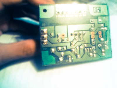
The schematic above can be used for supply on color TV for all type TV circuit. But we need to know how much voltage needed by the circuit of color Television. To set the output voltage, the setting on VR1 1K ohm. Required input voltage 300V DC which is already on TV circuit, so we just take a 300V dc voltage existing on the TV circuit, and for a circuit supply voltage on our TV cut the line PCB and connected with this universal switching power supply.For the transformer we can use the TV regulator transformer.

- R1 = 33R 5W
- R2 = 330R 1W
- R3 = 2K2
- R4 = 47K
- R5 = 2K7
- R6 = 22K
- R7 = 390K
- R8 = 47R 1W
- C1 = 100uF 25V
- C2 = 1n2 2KV
- C3 = 18n
- C4 = 18n
- D1 = 1N4148
- D2 = 1N4148
- D3 = ZD 12V
- D4 = 1N4007
- D5 = 1N4007
- VR1 = 1K
- ZD1 = Zener 6V
- T1 = TV regulator transformer
- Q1 = K2847
- Q2 = C2328A
 |
| PCB line |
 |
| Finishes circuit |
Sunday, October 27, 2013
6 to 12 Volt Power Supply Inverter
This inverter circuit can provide up to 800mA of 12V power from a 6V supply. For example, you could run 12V car accessories in a 6V (British?) car.
The circuit is simple, about 75% efficient and quite useful. By changing just a few components, you can also modify it for different voltages.

Part List:
R1, R4 2.2K 1/4W Resistor
R2, R3 4.7K 1/4W Resistor
R5 1K 1/4W Resistor
R6 1.5K 1/4W Resistor
R7 33K 1/4W Resistor
R8 10K 1/4W Resistor
C1,C2 0.1uF Ceramic Disc Capacitor
C3 470uF 25V Electrolytic Capcitor
D1 1N914 Diode
D2 1N4004 Diode
D3 12V 400mW Zener Diode
Q1, Q2, Q4 BC547 NPN Transistor
Q3 BD679 NPN Transistor
L1 See Notes
MISC Heatsink For Q3, Binding Posts (For Input/Output), Wire, Board
Next full text...
The circuit is simple, about 75% efficient and quite useful. By changing just a few components, you can also modify it for different voltages.
Part List:
R1, R4 2.2K 1/4W Resistor
R2, R3 4.7K 1/4W Resistor
R5 1K 1/4W Resistor
R6 1.5K 1/4W Resistor
R7 33K 1/4W Resistor
R8 10K 1/4W Resistor
C1,C2 0.1uF Ceramic Disc Capacitor
C3 470uF 25V Electrolytic Capcitor
D1 1N914 Diode
D2 1N4004 Diode
D3 12V 400mW Zener Diode
Q1, Q2, Q4 BC547 NPN Transistor
Q3 BD679 NPN Transistor
L1 See Notes
MISC Heatsink For Q3, Binding Posts (For Input/Output), Wire, Board
source:LINK
Wednesday, October 16, 2013
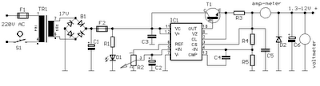
1 3 12 2 VDC Variable Power Supply
Power supply circuit to generate output below were variations between 1.3V DC to 12.2V DC with 1A current.
Next full text...
In addition, the power supply circuit is also equipped with over-current protection or shield against belebih flow. Power supply circuit is very simple, but the quality is quite good, made her basiccally regulator IC LM723 is a fairly legendary.
Monday, October 14, 2013
90 Watt Switching Power Supply
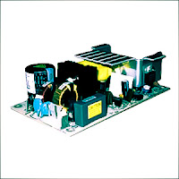
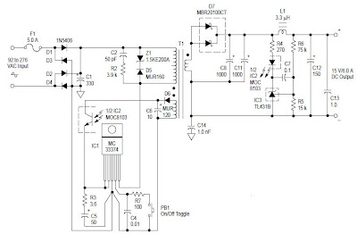
Switching Power Supply in this article are able to supply power 90 Watt. Switching Power Supply series is built directly from an AC network system using special IC MC33374 switching power supply in the form of High Voltage Power Switching Regulator and with external components to the other.
IC MC33374 IC is a switching power supply designed to operate with an AC voltage source and works as a power switching converter with flyback technique. Switching Power Supply Series has a 15 volt DC output with current up to 6 Ampere.
IC MC33374 IC is a switching power supply designed to operate with an AC voltage source and works as a power switching converter with flyback technique. Switching Power Supply Series has a 15 volt DC output with current up to 6 Ampere.
 |
| 90 Watt Switching Power Supply Schematic |
Series 90 Watt Switching Power Supply works by menyearahkan AC source is then used to activate the converter MC33374 system. The output of transformer switching converter MC33374 searahkan again later on as a DC voltage supply to be used for electronic devices.
Wednesday, October 9, 2013
1 3V DC to 12 2V DC Regulator Power Supply
Power supply circuit to generate output below were variations between 1.3V DC to 12.2V DC with 1A current.
In addition, the power supply circuit is also equipped with over-current protection or shield against belebih flow. Power supply circuit is very simple, but the quality is quite good, made her basiskan regulator IC LM723 is a pretty legendary.
In addition, the power supply circuit is also equipped with over-current protection or shield against belebih flow. Power supply circuit is very simple, but the quality is quite good, made her basiskan regulator IC LM723 is a pretty legendary.
Description:
R2 to set the output voltage. The maximum current is determined by R3, over-current protection circuit inside the LM723 to detect the voltage on R3, if it reaches 0.65 V, the voltage output will be off her. So the current through R3 can not exceed 0.65 / R3 although output short-circuit in his.
C3 and C4 are ceramic capacitors, as much as possible directly soldered to the PCB, this is because the LM723 is prone to oscillation that is not cool.
LM723 works with 9.5V input voltage to 40 V DC and the LM723 can generate its own current of 150mA when the output voltage is not more than 6-7V under input voltage.
Specifications:
Output (value estimated):
Vmin = (R4 + R5) / (R5 * 1.3)
Vmax = (7.15 / R5) * (R4 + R5)
Imax = 0.65/R3
Max. Power on R3: 0.42/R3
Min. DC Input Voltage (pin 12 to pin 7): Vmax + 5
Component List:
B1 40V/2.5A
C1 2200uF (3300uF even better)
C2 4.7uF
C3 100nF
C4 1NF
C5 330nF
C6 100uF
Green LED D1
D2 1N4003
F1 0.2A F
F2 2A M
IC1 LM723 (in a DIL14 plastic package)
R1 1k
R2 Pot. 5k
R3 0.56R/2W
R4 3.3k
R5 4.7k
S1 250V/1A
T1 2N3055 on a heatsink 5K / W
TR1 220V/17V/1.5
source [link]
Friday, October 4, 2013
5V 10A output switching power supply
The Schematic above shows a 10A power suplly with a 5V output and with power 50W. It is a flyback converter operating in the continuous mode. The circuit features a primary side and secondary side controller with full protection from fault conditions such as overcurrent. After the fault condition has been removed the power supply will enter the soft start cycle before recomming normal operation.

Resistor
R1_____100Ω
R2_____1Ω 1W
R3_____10Ω
R4_____100KΩ
R5_____0.33Ω 1W
R6_____10KΩ
R7_____390Ω
R8_____22KΩ
R9_____68Ω
R10____10Ω
R11____3.3Ω
RL_____5Ω 10W
Capacitor
C1_____0.022uF 400V
C2_____470uF 250V
C3_____470uF
C4_____220pF
C5_____470pF
C6_____2200pF
C7_____270pF
C8_____39pF
C9_____11,000uF
C10____10uF
C11____0.047uF
Diode
D1____1N4937
D2____MBR1035
M1____Diode Bridge
Inductor , Transformator
L1_____25uH
T1_____Lp - 9 mH = 1 : 15
T2_____50 uH. n = 1: 3
Transistor
Q1____BUZ80A
Q2____GE IRF823
Thursday, October 3, 2013
Power Supply Variable 1 3V 12 2V 1A Circuit
Power supply circuit to generate output below were variations between 1.3V DC to 12.2V DC with 1A current.
In addition, the power supply circuit is also equipped with over-current protection or shield against belebih flow. Power supply circuit is very simple, but the quality is quite good, made her basiskan regulator IC LM723 is a pretty legendary.
In addition, the power supply circuit is also equipped with over-current protection or shield against belebih flow. Power supply circuit is very simple, but the quality is quite good, made her basiskan regulator IC LM723 is a pretty legendary.
Description:
R2 to set the output voltage. The maximum current is determined by R3, over-current protection circuit inside the LM723 to detect the voltage on R3, if it reaches 0.65 V, the voltage output will be off her. So the current through R3 can not exceed 0.65 / R3 although output short-circuit in his.
C3 and C4 are ceramic capacitors, as much as possible directly soldered to the PCB, this is because the LM723 is prone to oscillation that is not cool.
LM723 works with 9.5V input voltage to 40 V DC and the LM723 can generate its own current of 150mA when the output voltage is not more than 6-7V under input voltage.
Specifications:
Output (value estimated):
Vmin = (R4 + R5) / (R5 * 1.3)
Vmax = (7.15 / R5) * (R4 + R5)
Imax = 0.65/R3
Max. Power on R3: 0.42/R3
Min. DC Input Voltage (pin 12 to pin 7): Vmax + 5
Component List:
B1 40V/2.5A
C1 2200uF (3300uF even better)
C2 4.7uF
C3 100nF
C4 1NF
C5 330nF
C6 100uF
Green LED D1
D2 1N4003
F1 0.2A F
F2 2A M
IC1 LM723 (in a DIL14 plastic package)
R1 1k
R2 Pot. 5k
R3 0.56R/2W
R4 3.3k
R5 4.7k
S1 250V/1A
T1 2N3055 on a heatsink 5K / W
TR1 220V/17V/1.5
Tuesday, October 1, 2013
Type of UPS Uninterruptible Power Supply
UPS design of the model is divided into several types that produce different performance characteristics:
A. Standby
2. Line Interactive
3. Double Conversion On-Line
4. Delta Conversion On-Line
Standby UPS typesThis type is commonly used by home users for the Presidency with their PC. UPS to be able to do this type of filtration against power failures and flow management, in addition to design efficient, small size and inexpensive.
Line Interactive UPS types
 UPS is the type most often used in small business unit, web developer, and a number of servers located in government departments. Because, in addition to having high levels of reliability, this type also have the ability to adjust the voltage that is sufficient
fine.
UPS has an inverter is always connected to the output of the UPS system to convert the power from batteries into AC. In normal circumstances, the Inverter will perform battery charging. While in a state of power outages, Transfer Switch will close and drain power from the batteries to the UPS output. Position that is always connected to the inverter output filter provides additional power. This makes the type of UPS is widely used for server and electrical conditions are not too good.
Double Conversion type UPS On-Line
This type is most common for UPS with power more than 10kVA. These types have in common with the type of Standby. Only this type has a power source located on the inverter, not the AC power source. In this type, the main electricity supply interruption will not trigger a transfer switch for the incoming AC power to the central input to charge the batteries that provide power to the Inverter located at the output. Therefore, when the AC power is disconnected, the flow of energy will be transferred immediately without taking a break when the transfer occurs. This type of UPS above shows the performance of the average. Can be said of this type of approach the ideal of a UPS, unfortunately this type of heat is high enough.
UPS type Delta Conversion On-Line
Almost the same as the Double Conversion type, type Delta used to always supply voltage Inverter. When the power supply is interrupted, this type do the same with Double Conversion type. Delta Conversion has two functions, the first is to control the input power characteristics. While the second function is to control the input current to direct the process of charging the battery system. The thing to remember is to minimize this type of energy is wasted. In addition, it has a high compatibility to various types of generators and reduce the need for the use of cables.
Saturday, September 21, 2013
Multiple output switching power supply circuit
This power supply uses two VN400A 400 Volts MOSFETs in a half-bridge power switch configuration. Each output consists of +5V at 20 A and 15 V at 1 A . Three-terminal regulators are used for the low-currents outputs , either 12 Volts or 15 Volts can be made available with a simple change in the transformer secondary windings. Schematic diagram below :

IC TL494 switching regulator IC provides pulse-with modulation control and drive signals for the power supply , The upper MOSFET , Q7 , in the power switch stage is driven by a simple transformer drive circuit. The lower MOSFET , Q6 , since it ground referenced , is directly driven from the control IC.
Friday, September 20, 2013
5 Volt Switching Regulator Power Supply
The switching regulator power supply used LM2575-5.0 on this schematic. You can make the stable voltage by using the 3 terminal regulator like LM317. However, because the output electric current and the inputted electric current are the same approximately, the difference between the input electric power (The input voltage x The input electric current) and the output power (The output voltage x The output current) is consumed as the heat with the regulator. Because it is, the efficiency isn�t good.
Data sheet for LM2575
SIMPLE SWITCHER 1A Step-Down Voltage Regulator
http://www.national.com/pf/LM/LM2575.htm
Subscribe to:
Posts (Atom)