Showing posts with label tv. Show all posts
Showing posts with label tv. Show all posts
Saturday, January 25, 2014
TV Protect Circuit Dead or Damaged
Television set equipped with a circuit protector, then there are several possibilities that could occur if there is a problem on one of the circuits. Protect circuit horizontal part - When turned on the horizontal plane will live for a while, but then died again. At the time of death when measured on the horizontal driver indicates that no drive signal. If the power jack unplugged then try to turn on again then repeated a similar incident will happen again. But if if the base of the transistor or transistor try to open removable drive signal was viable.
Protect circuit of microcontroll - If checked the voltage at pin microcontrol power on-off control, power control is turned on when the plane going "on" for a while then back "off". If you unplugged the power jack will power "on" again, but briefly and then keep coming back "off". On certain models sometimes die when the aircraft was marked with the blazing LED indicators blink. Protect circuit tube - aircraft can be turned on but a dark raster.
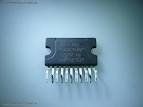 |
| Protect IC |
Tested voltage raster screen can be raised to normal flame or flame a horizontal line. Protect circuit the power supply - if enabled aircraft B + voltage of power supply there for a while but then lost or drops. Or the power supply voltage drops and there is but little rocking voltage, which is caused due to power supply to the death over and over again and again. There are models of televisions that do not use the protector system at all, there is only one system that uses a surge protector, but there are also some systems which use a surge protector as well. System protectors are made available for specific purposes. Keep track of the damage that led to protect circuit is sometimes difficult, because it always turns itself off the plane before we can make measurements. By getting to know a wide range of system protectors and understand how it works it will help overcome these difficulties.
Various kinds of protectors television system:
- Protectors x-ray
- Vertical Protectors
- Protectors B + over current (OCP)
- Protectors B + over voltage (OVP)
- ABL Protectors
- Supply voltage surge protector (if short or broken)
- Protectors white balance
- Protectors circuit power supply (SMPS)

Sunday, December 22, 2013
IR illuminator for Night Vision Tv Cameras and Scopes
This source uses LEDs and an astable oscillator to control the switch, duty-cycle, and effective IR illumination output.
Circuit Diagram

Circuit Diagram
Friday, December 20, 2013
Main function of TV tuner
 The main function of the tuner is to select the RF signals from the desired frequency spectrum wave on VHF and UHF and more signs in the air Changing RF variable into a fixed IF frequency and to provide sufficient strengthening to cover the original data that has been transmitted.
Block diagram of a series of TV tuner to receive the frequency VHF / UHF

Operational Tuner [Theoretical]
Tuner is controlled by a microprocessor in the TV chassis, which functions to receive / select a frequency. Exchange of information is channeled through the terminal Address, Clock and Data.
In the tuner, there are ICs that function to translate the instruction / data so that the tuner can function to select the desired frequency. The IC consists of some combination of series, including PLL, Local Oscillator [VCO], Mixer and IF amplifier. Everything artifacts in one chip / one chip. For further analysis, CXA3135 IC with I2C format will be taken as an example.
Tuesday, December 17, 2013
TV Remote Control Jammer
This circuit confuses the infra-red receiver in a TV. It produces a constant signal that interferes with the signal from a remote control and prevents the TV detecting a channel-change or any other command. This allows you to watch your own program without anyone changing the channel !! The circuit is adjusted to produce a 38kHz signal. The IR diode is called an Infra-red transmitting Diode or IR emitter diode to distinguish it from a receiving diode, called an IR receiver or IR receiving diode. (A Photo diode is a receiving diode).
TV Remote Control Jammer Circuit diagram:

There are so many IR emitters that we cannot put a generic number on the circuit to represent the type of diode. Some types include: CY85G, LD271, CQY37N (45¢), INF3850, INF3880, INF3940 (30¢). The current through the IR LED is limited to 100mA by the inclusion of the two 1N4148 diodes, as these form a constant-current arrangement when combined with the transistor and 5R6 resistor.
TV Remote Control Jammer Circuit diagram:
There are so many IR emitters that we cannot put a generic number on the circuit to represent the type of diode. Some types include: CY85G, LD271, CQY37N (45¢), INF3850, INF3880, INF3940 (30¢). The current through the IR LED is limited to 100mA by the inclusion of the two 1N4148 diodes, as these form a constant-current arrangement when combined with the transistor and 5R6 resistor.
Monday, November 18, 2013
Main function of TV tuner
The main function of the tuner is to select the RF signals from the desired frequency spectrum wave on VHF and UHF and more signs in the air Changing RF variable into a fixed IF frequency and to provide sufficient strengthening to cover the original data that has been transmitted.Block diagram of a series of TV tuner to receive the frequency VHF / UHF
Operational Tuner [Theoretical]
Tuner is controlled by a microprocessor in the TV chassis, which functions to receive / select a frequency. Exchange of information is channeled through the terminal Address, Clock and Data.
In the tuner, there are ICs that function to translate the instruction / data so that the tuner can function to select the desired frequency. The IC consists of some combination of series, including PLL, Local Oscillator [VCO], Mixer and IF amplifier. Everything artifacts in one chip / one chip. For further analysis, CXA3135 IC with I2C format will be taken as an example.
Power amplifier compatible with TV audio

In this amplifier circuit using IC TDA8944J as the main amplifier with dual-channel audio amplifier with 2 x 7W output power at 8 Ω impedance. And a minimum supply voltage of 9-18 Volts. In this ic contains two Bridge Tied Load or BTL amplifier.
The circuit is often found in audio amplifier in a series of television, besides TDA2003, TDA2006 and so forth. PCB for a series of amplifiers using IC TDA8944J is very compatible with all other types of IC in IC TDA894X family unit , and below is a schematics.

Monday, October 28, 2013
Universal switching power supply for TV
The schematic above can be used for supply on color TV for all type TV circuit. But we need to know how much voltage needed by the circuit of color Television. To set the output voltage, the setting on VR1 1K ohm. Required input voltage 300V DC which is already on TV circuit, so we just take a 300V dc voltage existing on the TV circuit, and for a circuit supply voltage on our TV cut the line PCB and connected with this universal switching power supply.For the transformer we can use the TV regulator transformer.

- R1 = 33R 5W
- R2 = 330R 1W
- R3 = 2K2
- R4 = 47K
- R5 = 2K7
- R6 = 22K
- R7 = 390K
- R8 = 47R 1W
- C1 = 100uF 25V
- C2 = 1n2 2KV
- C3 = 18n
- C4 = 18n
- D1 = 1N4148
- D2 = 1N4148
- D3 = ZD 12V
- D4 = 1N4007
- D5 = 1N4007
- VR1 = 1K
- ZD1 = Zener 6V
- T1 = TV regulator transformer
- Q1 = K2847
- Q2 = C2328A
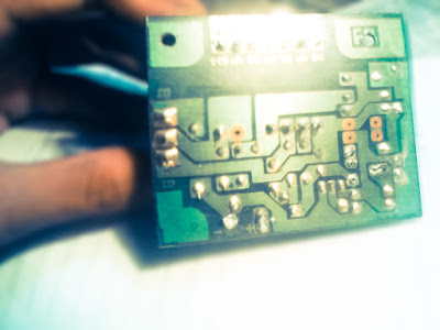 |
| PCB line |
 |
| Finishes circuit |
Saturday, October 12, 2013
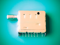
Solving the problem on tv tuner
1. Image does not exist and there is no sound, raster speckled thick.
2. No picture no sound, or otherwise.
3. Channel switching the channel itself.
4. Image blocking white or blue.
How to check the tuner and the IF is to remove the tuner from the PCB and connected by cable to the IF path, BM and Ground, then prepared using the pin on the tuner. Then the television was turned on, the antenna is connected to the antenna socket, and RV or potensio rotated slowly to choose the television channel when the tuner is in normal condition, the signal from the antenna to be acceptable, the picture and sound, and the channels do not move themselves. To damage its own channel switch and checked the normal manner stated above, the location of damage on the section of the program.
Thursday, September 19, 2013
Power amplifier compatible with TV audio
In this amplifier circuit using IC TDA8944J as the main amplifier with dual-channel audio amplifier with 2 x 7W output power at 8 Ω impedance. And a minimum supply voltage of 9-18 Volts. In this ic contains two Bridge Tied Load or BTL amplifier.
The circuit is often found in audio amplifier in a series of television, besides TDA2003, TDA2006 and so forth. PCB for a series of amplifiers using IC TDA8944J is very compatible with all other types of IC in IC TDA894X family unit , and below is a schematics.
Subscribe to:
Posts (Atom)