Showing posts with label power. Show all posts
Showing posts with label power. Show all posts
Friday, January 24, 2014
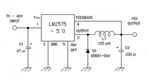
5 Volt Switching Regulator Power Supply
The switching regulator power supply used LM2575-5.0 on this schematic.
You can make the stable voltage by using the 3 terminal regulator like LM317. However, because the output electric current and the inputted electric current are the same approximately, the difference between the input electric power (The input voltage x The input electric current) and the output power (The output voltage x The output current) is consumed as the heat with the regulator. Because it is, the efficiency isn�t good.
You can make the stable voltage by using the 3 terminal regulator like LM317. However, because the output electric current and the inputted electric current are the same approximately, the difference between the input electric power (The input voltage x The input electric current) and the output power (The output voltage x The output current) is consumed as the heat with the regulator. Because it is, the efficiency isn�t good.
Data sheet for LM2575
SIMPLE SWITCHER 1A Step-Down Voltage Regulator
http://www.national.com/pf/LM/LM2575.htm
Sunday, January 12, 2014
Inverter 12V to 115V with 25 W power output
Low power inverter schematic are only use 9 components , one of which IC 556 , TIP120 NPN Darlington transistor.And turns 10 to 16 Vdc into 60 HZ, output 115 V square-wave power to operate ac equipment up to 25 W. In the circuit first ic originally hires as a timer chip m for stabilizatiom oscilator with components R1 and C1 setting frequency oscilator. Then the two transistor driver, drive the transformer push-pull fashion, When one transistor is biased on , the other circuit cut-off . The transformer is a 120V/18Vct unit that is connected backwards, so that it steps the voltage up rather than down. Oscilator circuit operates from about 4 to 16 V for stable output.
Part List :
R1 = 1K
R2 = 12K
R3 = 1K
R4 = 1/4W
C1 = 1uF
IC = 556
Q1 = TIP120
Q2 = TIP120
T1 = 120V 18VCT

Thursday, January 9, 2014
Mosfet Amplifier 20Watt Output Power
This audio amplifier showed in this circuit diagram , is a very simple and efficiency audio amplifier circuit based on the TDA1308 integrated class-AB stereo headphone . The device is fabricated in a 1 mm Complementary Metal Oxide Semiconductor (CMOS) process and has been primarily developed for portable digital audio applications.
You can use this circuit diagram with TDA1308 or TDA1308A , the difference between the TDA1308 and the TDA1308A is that the TDA1308A can be used at low supply voltages. The maximum output power that can be obtained with this circuit is around 80mwatts. This audio amplifier circuit requires a very low voltage power supply : from 3 to 7 volts for single supply or 1.5 to 3 volts for dual supply , for TDA1308 .
The TDA1308A supports a low voltage input down to 1.2 volts , but the typical power supply required for both circuits is 5 volts for single supply and 2.5 volts for dual supply .
As you can see the circuit requires very few external components and can be configured to work in stereo or mono configuration.
Thursday, December 26, 2013
70W Audio Power Amplifier Mono
DA1562Q si a 70 W high efficiency power amplifier with diagnostic facility. The TDA1562Q contains a mono class-H BTL output power amplifier.At low output power, up to 18 W, the device operates as a normal BTL amplifier.
70W Audio Power Amplifier Mono Circuit Diagram

When a larger output voltage swing is required, the internal supply voltage is lifted by means of the external electrolytic capacitors. Due to this momentarily higher supply voltage the obtainable output power is 70 W.
The heatsink should be designed for use with music signals. If the case temperature exceeds 120 °C, the device will switch back from class-H to class-B operation. The high power supply voltage is then disabled and the output power is limited to 20 W. When the supply voltage drops below the minimum operating level, the amplifier will be muted immediately.
70W Audio Power Amplifier Mono Circuit Diagram
The heatsink should be designed for use with music signals. If the case temperature exceeds 120 °C, the device will switch back from class-H to class-B operation. The high power supply voltage is then disabled and the output power is limited to 20 W. When the supply voltage drops below the minimum operating level, the amplifier will be muted immediately.
Wednesday, December 25, 2013
200W Stereo High Power Amplifier LM3886
This audio amplifier designed uses two LM3886 per channel, in parallel circuit, based on the PA100 parallel amplifier detailed in National Semiconductors application note - AN1192. This amplifier can deliver about 50W into a 8-ohm speaker and 100W into a 4-ohm speaker. This is a stereo amplifier and therefore 4 LM3886s are used.
 The LM3886 circuit is in a non-inverted configuration, so the input impedance is determined by the input resistor R1, i.e. 47k. The 680 ohm and 470pF resistor capacitor filter network is used to filter out the high frequency noise at the RCA input. The 220pF C4 and C8 capacitors are used to shot out the high frequency noise at the LM3886 input pins.
I used high quality audio grade capacitors at several locations: 1uF Auricap at the input for DC blocking, 100uF Blackgate for C2 and C6, and 1000uF Blackgate at the supply filter.
The PCB is designed in a way that the power ground is separated from the signal ground, as you can see from the below layout. The signal ground is located in the middle and surrounded by the power ground. There is a thin trace near C5 connecting them. The PCB layout is done by using PADS PowerPCB 5.0. I think it is a powerful layout software.
Amplifier Printed Circuit Board (PCB)
Amplifier Power Supply
The power supply used is a regulated power supply. I used 10000uF per rail before the LT1083 regulator. After the regulator, I have 100uF on the regulator board. The advantage of using regulator is that the power supply ripple voltage is removed. If power regulation is not used, I can hear very little 50/100Hz hum from the speaker.
The high current MUR860 diode is used to ensure high current flow. The voltage regulator used is LT1083, it can provide about 8A of current. Transformer used here is a 500VA 2x 25V. The power supply is then regulated by 2 LT1083, after the regulation, the voltage is 30V.
I did some DC measurement and the result is quite good, I got 7 mV of DC offset at the speaker terminal. The voltage difference between the output of the 2 chips is less then 1 mV.
The sound of this amplifier is similar to my LM3875 amplifier, which is very clean and detail. It has no hum, no hiss and no noise. Compared to the LM3875 Gainclone, this amp can deliver twice the power to my 4-ohm speaker, and it improves the dynamics and bass punch a lot.
Source :http://www.shine7.com/audio/pa100.htm
 |
| LM3886 Power Amplifier Schematics |
The PCB is designed in a way that the power ground is separated from the signal ground, as you can see from the below layout. The signal ground is located in the middle and surrounded by the power ground. There is a thin trace near C5 connecting them. The PCB layout is done by using PADS PowerPCB 5.0. I think it is a powerful layout software.
Amplifier Printed Circuit Board (PCB)
 |
| Amplifier Printed Circuit Board Bottom |
 |
| Amplifier Printed Circuit Board Top |
 |
| Amplifier Printed Circuit Board |
The power supply used is a regulated power supply. I used 10000uF per rail before the LT1083 regulator. After the regulator, I have 100uF on the regulator board. The advantage of using regulator is that the power supply ripple voltage is removed. If power regulation is not used, I can hear very little 50/100Hz hum from the speaker.
The high current MUR860 diode is used to ensure high current flow. The voltage regulator used is LT1083, it can provide about 8A of current. Transformer used here is a 500VA 2x 25V. The power supply is then regulated by 2 LT1083, after the regulation, the voltage is 30V.
 |
| Power Supply Recomended |
The sound of this amplifier is similar to my LM3875 amplifier, which is very clean and detail. It has no hum, no hiss and no noise. Compared to the LM3875 Gainclone, this amp can deliver twice the power to my 4-ohm speaker, and it improves the dynamics and bass punch a lot.
Source :http://www.shine7.com/audio/pa100.htm
Tuesday, December 24, 2013
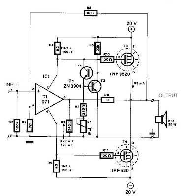
65W Power Amplifier Circuits with HEXFET
 65W Power Amplifier Circuits with HEXFET
A average ability amplifier that is characterized by a lot of acceptable complete quality, but accompanying is actual simple in the construction. Him uses, abundant time in my alive loudspeakers. In his achievement date abide the actual acceptable FET transistors, technology HEXFET, transistor which are controlled by voltage and no by accepted as the classically bipolar transistors. The ambit has balanced designing, absolute appropriately the harmonic baloney problem.
All the transistors that are acclimated in the ambit are simple and they abide in big clearings in the market. The pairs of cogwheel amplifiers Q1-2 and Q3-4 should be akin amid them and abreast the one in the other. Appropriately you can buy abundant transistors of types BC550C and BC560C, and with a multimeter you bout amid them creating pairs with aforementioned characteristics, ensuring appropriately compatible behavior in the temperature changes etc. Networks RC from the R7/C3 and R12/C4 abatement the bandwidth of cogwheel amplifiers and ability amplifier in the 6.5MHZ. Resistors R8-9-10-11 action as bounded acknowledgment in the cogwheel amplifiers convalescent the linearity. The cogwheel amplifiers are supplied with connected accepted from him accepted sources Q5 and Q6. The bent of accepted sources becomes from the aggregate of diodes LED D1, D2 and R20.
This becomes because the aggregate transistor/LED ensures big thermic stability, for this acumen should they are in actual abreast ambit [1]. With the TR1 trimmer we adapt the bent accepted of achievement ability stage. For this acumen Q8 should acquisition itself on the heatsink so that it ensures thermic adherence in the bias, so that it does not change with the temperature changes. The resistors R32-33 appearance a bounded acknowledgment bronchus in the achievement stage, because this functions as voltage amplifier.
With the TR1, R3-4, C14 we adapt the amplifier achievement DC account voltage, abreast in the zero. The transistors Q8-10-11-12-13, [Fig.1] should are placed on heatsink, abacus amid the transistors and the heatsink of acceptable affection leaves mica and ointment. Inductor L1 is constituted by 6 coils of cloistral cupreous wire of bore 1.5mm, with centralized inductor bore of 16mm
Friday, December 20, 2013
Tips for Choosing a quality Power Amplifier
Here are some tips you need to note:
1. Pick of the power that suits your needs. For personal use such as exercise, etc., is sufficient to choose an amplifier with a power of 15-20 watts. In most small power amplifiers are already available facilities such as Head Phone jack (eg Guitar Amplifier Laser 20) which is very useful especially for young people who have a habit of playing music until midnight. By leveraging these channels to Head Phone, then secured another household or neighbors will not be disturbed our music sound. Sound good hasilnya.Apabila amplifier system we will use to train together in a full band with drums, etc., then you should choose a larger power amplifier that is 70 watts or above. Thus the sound produced from the amplifier and sound system will not be drowned by the sound of pounding and pounding beat Drum.Untuk use on stage, you will need a higher power that is at least 125 watts or more, because this amplifier will be able to once we use as a monitor of musical instruments were playing.
2. Choose the facilities we need. Do not buy amplifiers which have facilities that we do not really need when it is increasing the price we pay. Unless the same price we can get better facilities, there is no harm in our selection.
3. Choose a good quality amplifier. If we need an amplifier to your keyboard, then it is advisable to select an amplifier that does not change the color of the original sound generated by the keyboard musical instrument they will be (flat). There are many amplifiers that produce different sounds from the original sound, if this happens there will be other voices that would reduce the original character of the actual sound produced by the keyboard because of the addition or subtraction of a particular frequency. Usually this happens at a very low frequency (low bass) or very high frequency (high treble). (Try the sound system rental, sound rental service) For amplifiers Electric Guitar and Electric Bass this (flat characteristic) does not apply because it specifically for these two types of instruments are required specificity of character frequency. Basically for Electric Guitar amplifier output is not needed for low frequency and high. For Electric Bass needed a low frequency, but not required a high frequency. We can learn from the rental place and the sound system rental-quality musical instrument.
4. Model and performance amplifier can be considered final. The desired model will depend on individual taste. A good model according to a person, not necessarily a good thing according to those who lainnya.Pada most professional musicians model will be the last option or not too overlooked. They will be more concerned with the quality and facilities of the amplifier. Maybe we can find also in the rental services professional sound and musical instrument rental place bagus.Demikian brief tips on choosing an amplifier, hopefully this can help to determine the right choice before you buy an amplifier and produce sound quality music is also of course .
Tips for Choosing Quality Amplifier
1. Pick of the power to suit your sound system. For personal use such as exercise is sufficient to choose an amplifier with 1-20watt power. In most electronic devices / small power amplifiers are already available facilities such as head phone jack (eg laser20 guitar amplifier) is very useful especially for young people who have a habit of playing music until midnight. By leveraging the channel for these headphones, then secured another household or neighbors will not be disturbed "attraction" we. If the amplifier sound system we will use to train together in a group full band * with drum and band instrument, then you should choose a power amplifier 70watt or above. Thus the sound produced from the amplifier will not be drowned by the sound of pounding and pounding drum beats. For use on stage, you will require more resources than most, namely at least 125watt or more, because this amplifier will be at the same we use as a monitor of musical instruments were playing.
2. Select the facilities we need. Do not buy a multimedia system / amplifier that has the facilities that we do not really need, if it is increasing the price we pay. Unless the same price we can get better facilities, there is no harm in our selection.
3. Choose a good quality amplifier. If we need an amplifier to your keyboard, then it is advisable to select an amplifier that does not change the original color generated by the keyboard (flat). There are many Indonesian musical instrument amplifier that produces a different sound from the original sound, if this happens there will be other voices that would reduce the original character of the actual sound produced by the keyboard because of the addition or subtraction of a certain frequency speaker system. Usually this happens at a very low frequency. (Low bass) or very high frequency (high treble). To Lighting System, Electric Amplifier Electric Bass Guitar and this (flat characteristic) does not apply because it specifically for these two types of instruments required specificity of character frequency. Basically for Electric Guitar not dipelukan amplifier output for low frequencies and high. For Electric Bass needed a low frequency, but not required a high frequency.
4. Models and appearance can be thought being given to the last amplifier. The desired model will depend on individual taste. A good model according to a person not necessarily a good thing by other people.
In most professional musicians, models will be the last option or not too overlooked. They will be more concerned with the quality and features of the amplifiers for musical instruments. But if you are confused, you could just rent equipment or hire sound system rental equipment.
Monday, December 16, 2013
Protection of the Mosfet in flyback power supply
PKC-136 PEAK CLAMP CHARACTERISTICS VBR 160Vdc VDRM 700Vdc P 1.5W. See Circuits Diagram below :
Feature :
- Protection of the Mosfet in flyback power supply
- TRANSIL™ and blocking diode in a single package BENEFITS
- Accurate voltage clamping regardless load
- Reduced current loop
- Reduced EMI emission
- High integration
- Fast assembly
- Reduced losses in stand by mode
Next full text...
 |
| Protection of the Mosfet in flyback power supply |
- Protection of the Mosfet in flyback power supply
- TRANSIL™ and blocking diode in a single package BENEFITS
- Accurate voltage clamping regardless load
- Reduced current loop
- Reduced EMI emission
- High integration
- Fast assembly
- Reduced losses in stand by mode
Sunday, December 15, 2013
200W power amplifier complete power supply
This 200W power amplifier circuit using IC STK 4050.
STK 4050 is a power amplifier module is very powerful, because the IC is already a module then only needed a little extra components to build a reliable 200W Power Amplifier. Here is a picture series of Power Amplifier ICs 200W use STK 4050 complete with its power supply:
STK 4050 is a power amplifier module is very powerful, because the IC is already a module then only needed a little extra components to build a reliable 200W Power Amplifier. Here is a picture series of Power Amplifier ICs 200W use STK 4050 complete with its power supply:
Tuesday, November 19, 2013
9V output switching power supply
By using the circuit you do not bother to roll up a transformer that is used to reduce voltage AC 220V to 7V ,9 V or 12V, etc. When using a large transformer we will find it hard to make transformator. by rolling hundreds or even thousands of times roll. But if you use this circuit a little just enough to roll trafo not to small, and its be relatively small.

R1________________________________680K
R2________________________________47K
R3________________________________100R
R4________________________________1K
R5________________________________1R
D1,D2,D3,D4,D7,D8,D9,D10__________1N4007
D5,D6_____________________________1N4148
C1________________________________2u2F 400V
C2________________________________2n2
C3________________________________47uF 25V
C4________________________________10n
C5________________________________470uF / 16V
Q1________________________________MJE13003
Q2________________________________S8050
This is construction of transformer. For the first toll 220 times , then after that wrap right on top of L2 , and L3 on L2.

Power Amplifier Circuit 2 x 20 W stereo with IC AN7156N
This circuit operate with IC AN7156N . You just can use this IC , because havnt similarity it. In this Circuit have 2 input IN R and IN L and have Output R and L . Voltage supply require 15 V , minimum voltage 9 V and maximum voltage 24V . And the voltage must DC voltage , and better the DC voltage filtering .
Maximum Output for 1 speaker 25 W , so this circuit have maximum output 2 X 25 W with minimum impedance 4 ohm. See this circuit schematic below :
 |
| Click image to view enlarge |
Monday, November 18, 2013
Power amplifier compatible with TV audio

In this amplifier circuit using IC TDA8944J as the main amplifier with dual-channel audio amplifier with 2 x 7W output power at 8 Ω impedance. And a minimum supply voltage of 9-18 Volts. In this ic contains two Bridge Tied Load or BTL amplifier.
The circuit is often found in audio amplifier in a series of television, besides TDA2003, TDA2006 and so forth. PCB for a series of amplifiers using IC TDA8944J is very compatible with all other types of IC in IC TDA894X family unit , and below is a schematics.

Sunday, November 17, 2013
Tube Power Amplifier 35W Push Pull
Tube Power Amplifier 35W Push Pull is made using a tube and eventually compiled configuration push-pull amplifier. Tube Power Amplifier 35W Push Pull tube til it using EL-34 as the amplifier end.
In the power amplifier that is made with a tube at a glance looks simple because the use of active components that are not complex. It should be noted that the use of tubes in Tube Power Amplifier 35W Push Pull require a high voltage supply, therefore in the process of making and finishing must be careful of high voltage and radiation. Detailed series of Tube Power Amplifier 35W Push Pull can be seen in the following figure. Tube Power Amplifier Series 35W Push Pull

Sign Components Tube Power Amplifier 35W Push Pull
R1 = 470K 0.5 W
R2-5 = 2K2 0.5W
R3 = 150K 0.5W
R4 = 220K 0.5W
R6-10 = 56K 0.5W
R7 = 3.9K 0.5W
R8 = 220R 0.5W
R9 = 1M 0.5W
R11 = 39K 1W
R12-23 = 180K 0.5W
R13-21 = 820K 0.5W
R14-22 = 5K6 0.5W
R15-20 = 680K 0.5W
R16-19 = 100K 0.5W
R17-18 = 3K3 1W
R24 = 470R 2W
TR1-2 = 470R 1W Variable (adj. 270Ω)
C1-3-6-7 = 0.1uf 630V
C2 = 220pF 600v
C4-5 = 16uF 550V
C8-9 = 0.1uF 630V
C10-14 = 0.47uF 630V
C11-13 = 25uF 40V
V1 = E80CC
V2 = E80CC
V3-4 = EL34
Rectifier tube = Z2C
Audio Transformer for T1 = 2x EL34 Push Pull
Power amplifier with tubes often become the choice for a small slewrate so that the resulting audio quality is guaranteed. Tube Power Amplifier 35W in the circuit that is required to supply a high DC voltage is +220 VDC ddengan order to work properly.
Wednesday, November 13, 2013
Power Supply with regulator output use IC uA723
This circuit operating with IC uA723 and add amplified with transistor TIP31 or similiar transistor with TIP31 . Input voltage for circuit about 10 - 40 volt DC , formerly of AC voltage 220 volts or 110 volts , then lowered by the transformer voltage to 30 volts. And the supply output voltage from 1 volt to 35 volt DC you can adjust it on potentiometer R2.
See this circuit power supply below :

Output voltage transformer used 10 to 40 Volts . On resistor Rsc is the current limit set resistor. Its value is calculated as :
Rsc = 0.65 Volt For Example : If you need current output 2.0 A
Rsc = 0.65 / 2.0 = 0.32 Ohm So , you must use 0.32 Ohm to current output 2.0 A
Monday, November 11, 2013
1 W low power audio amplifier circuit
This circuit based on IC TDA7233 or you can use IC TDA7233D . Minimum supply voltage 1,8 volts and aximum voltage 15 volts. Power Output 1 Watt with 1 Ohm impedance. This circuit include mute switch, which allows you to the mute sound completely.

Next full text...
Friday, November 8, 2013
Low Power Amplifier with digital volume control

Amplifier with digital volume control can we make predictably because the circuit is made simple with just single chip TDA8551. The series of Mini Amplifier With Digital Volume Control is a type BTL amplifier with 1 Watt.
Techniques for adjusting the volume in this series has been provided with a pin path control that is controlled by providing an input voltage VCC and GND. The series is also equipped with a selector mute, standby and operating.
Techniques for adjusting the volume in this series has been provided with a pin path control that is controlled by providing an input voltage VCC and GND. The series is also equipped with a selector mute, standby and operating.
 |
| Mini amplifier with digital volume control schematics |
Thursday, November 7, 2013
300W Power Amplifier Circuit with 2N773
Power Amplifier 300W with transistor 2N3773
This amplifier was designed to provide a use for the otherwise useless TO3 power transistors that many hobbyists have in their junk pile. With good construction the module is capable of high quality performance and is rated to 300 watts into a 4 ohm load depending on power supply. With the driver and output transistors specified it is limited to DC rails of +/- 70 volts.
 |
| Power Amplifier Circuit Diagram |
Wednesday, November 6, 2013
Dual Power Supply
To build (or else design) solitary. here are a a small number of things one must come about sensitive with, such in the role of the routing of prohibitive current leads, but these are without difficulty accomplished. The earliest gadget to point out is a apt transformer. I hint toroidal transformers preferably than the traditional "EI" laminated types for the reason that they branch out a reduced amount of magnetic flux and are compliment, allowing them to subsist installed in vogue slimmer hand baggage.
They resolve give various problems, such for instance elevated inrush current on switch on, which channel to facilitate lengthy blow fuses essential be used. representing the 60W amplifier, a nominal (filled load) supply of +/- 35V is vital, so a 25-0-25 secondary is ideal - however, escort Updates, lower. The circuit for the supply is given away below, and uses separate rectifiers, capacitors and fuses pro every one channel. merely the transformer is shared, so channel interactions are minimised. A single ±35V supply (i.e. using just a single association and put of filter capacitors) yearn for job immediately because well voguish the majority of luggage.
 |
| Dual Power Supply Circuit |
The 5A slow down-blow fuse given away is as it should be instead of a 300VA transformer, if a 120VA transformer is used, this be supposed to live compact to 2.5A (before 3A if 2.5A proves too awkward to search out). If you are even a minor fragment concerned roughly the fuse rating, phone the transformer manufacturer in support of the recommended charge for the transformer you force utilize. The correct fuse is life-threatening to ensure safety from electrical failure, which might conclusion participating in the equipment apt unsafe before causing a fire.
The capacitance used is not critical, but is somewhat dependent in the lead lones financial plan. I advocate 10,000uF capacitors, but they are fairly expensive so by the side of a pinch 4,700uF caps ought to be there fine - especially in the array revealed. what time unloaded (or else with individual light load), the voltage desire normally be somewhat privileged than 35 Volts. This is Ok, and ought to not cause distress to one amp. The voltage will fall in the same way as added current is drawn, and may well release less than 35V if a minute transformer (otherwise individual with unusually poor instruction) is used.
Two parts of this circuit are derogatory:
Mains wiring ought to exist cabled using official 240V rated insulated cable, and all terminations must be insulated to prevent unintended associate. The mains earth obligation be securely fixed firmly to the framework, afterward scraping away several paint or else other coating which might prevent dependable contact.
The centre-tap of the transformer and the ground points of apiece capacitor have to subsist connected to the major warning sign earth aspect via bodyguard duty copper wire, otherwise (rather) a copper motor vehicle-block. big currents emerge hip this part of the circuit, containing nasty current waveforms which are quite glad to invade your amplifier. The supply voltages duty live taken from the capacitors (not the join rectifiers) to prevent unwelcome hum and clatter.
after wiring the bridge rectifiers to the transformer, hook up exactly in the role of exposed to ensure with the purpose of move voltages (and currents) are dressed in time in favor of every one amp. If not, baffling hum signals may perhaps be present injected into the amps suggest path from bypass capacitors and the like. This is somewhat improbable but for giant caps are used on the amp board(s) - not recommended, by the way - but why take the expose?
association rectifiers must transpire the gigantic bolt-down 35A types (before something related) to ensure lowest feasible losses (these self-control not require an bonus heatsink - the carcass will normally be quite sufficient). The transformer primary voltage will apparently be real unwavering by the supply voltage during your area (i.e. 120, 220 or else 240) and be suited to the regional supply frequency. hint to facilitate all 50Hz transformers desire toil a moment ago fine by 60Hz, but more or less 60Hz diplomacy will overheat if used by the side of 50Hz.
The transformer ought to befall rated by a most minuscule of 120VA (Volt-Amps) on behalf of home-grown operation, but a 300VA transformer is recommended due to its exceptional government. available afar 300VA desire perform thumbs down informative determination, other than to dim the light such as it is crooked on. someplace it is potential, the pointer and power ground be supposed to be alive the same (this prevents the chance of an thrilling shock hazard be supposed to the transformer develop a succinct circuit amid primary and secondary. someplace this wish allocate ascend to ground loops and hum dressed in other equipment, use the method exposed.
The resistor R1 (a 5W wirewound resistor is suggested) isolates the low-voltage penetrating-current ground ball circuit, and the diodes D1 & D2 provide a shielding circuit in the event of a foremost difficulty. These diodes need just be situated low voltage, but a current rating of 5A or else greater is compulsory. The 100nF capacitor (C1) acts seeing that a abruptly circuit to telephone lines frequency signals, effectively foundation them. This ought to be a device with very fine high frequency response, and a monolithic clay is recommended.
800W high power mosfet amplifier
This amplifier can be used for practically any application that requires high power, low noise, distortion and excellent sound. Examples would be Sub-woofer amp, FOH stage amplifier, One channel of a very high-powered surround sound amplifier etc.
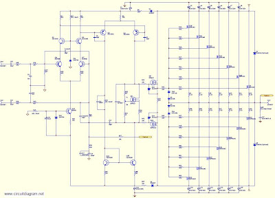
For detail explanation about how this circuit works include the large schematic diagram, power supply schematic diagram and complete component listing, link download this complete article.
Monday, November 4, 2013
Nmos Power Amplifier Series
Power Amplifier with quasi complementary model is the final power amplifier with the transistors of the same type (N all) or (P all), not using transistor pairs. Connecting post part 1, in section 2 is still to review mosfet power amplifier. Two output stage configurations capable of delivering up to 350 watts or up to 500 watts into a 4 ohm load.
 |
| Nmos Power Amplifier Series |
Final Set up And Adjustment
No attempt should be made to set up or test a power amplifier module that is not correctly mounted
on a heatsink. Make sure the main power supply is fused and the work area is clear. First check all
your work and make sure the output devices are insulated from heatsink. The set up is done without
an input or a load connected to the power amplifier.
1. Check the power supply is operating correctly and verify the rail voltages. Switch the power
supply off and check with a multimeter that the rail capacitors have discharged.
2. Correctly connect the ground, positive and negative leads to the power amp module.
3. Remove the PCB fuses and replace with 100 ohm 5 watt resistors. Connect a multimeter
that is set to the 20 volt scale across the positive rail 100 ohm resistor.
4. Check that the power supply connections are correct one last time and switch on. If the
multimeter reading goes off-scale, turn off immediately and find the problem. Check also the
100 ohm 5 watt resistors; they may have gone open cct.
5. If everything seems ok adjust VR2 to set the output stage bias current, by measuring the
voltage across the positive rail resistor. Adjust for a reading of 3 volts per output FET pair. I.e.
For a 6 FET board set for a voltage of 9 volts. This equates to a bias current of 30mA per
FET pair or 90 mA total. For a 10 FET board set for a voltage of 15 volts.
6. If everything seems ok, check the output offset voltage and adjust VR1 to achieve an offset of
less than 10 mV.
7. All being well switch off, back off the bias control trimmer (VR2) and replace the 100 ohm
resistors with 10 ohm 1 watt resistors. Switch on again and re-adjust VR2 to get 0.3 volts per
per FET pair across the positive rail 10 ohm resistor.
8. Switch off, remove the resistors and put the fuses back in. Switch on, re-check the offset
voltage and adjust with VR1 if necessary.
The amp module is ready, connect the input and output and enjoy.
Subscribe to:
Posts (Atom)