Showing posts with label high. Show all posts
Showing posts with label high. Show all posts
Wednesday, December 25, 2013
200W Stereo High Power Amplifier LM3886
This audio amplifier designed uses two LM3886 per channel, in parallel circuit, based on the PA100 parallel amplifier detailed in National Semiconductors application note - AN1192. This amplifier can deliver about 50W into a 8-ohm speaker and 100W into a 4-ohm speaker. This is a stereo amplifier and therefore 4 LM3886s are used.
 The LM3886 circuit is in a non-inverted configuration, so the input impedance is determined by the input resistor R1, i.e. 47k. The 680 ohm and 470pF resistor capacitor filter network is used to filter out the high frequency noise at the RCA input. The 220pF C4 and C8 capacitors are used to shot out the high frequency noise at the LM3886 input pins.
I used high quality audio grade capacitors at several locations: 1uF Auricap at the input for DC blocking, 100uF Blackgate for C2 and C6, and 1000uF Blackgate at the supply filter.
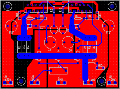
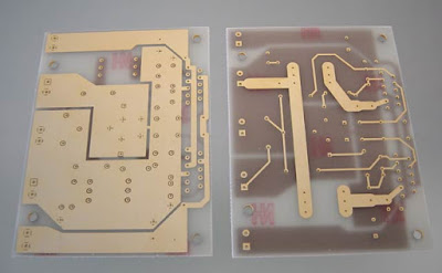
The PCB is designed in a way that the power ground is separated from the signal ground, as you can see from the below layout. The signal ground is located in the middle and surrounded by the power ground. There is a thin trace near C5 connecting them. The PCB layout is done by using PADS PowerPCB 5.0. I think it is a powerful layout software.
Amplifier Printed Circuit Board (PCB)
Amplifier Power Supply
The power supply used is a regulated power supply. I used 10000uF per rail before the LT1083 regulator. After the regulator, I have 100uF on the regulator board. The advantage of using regulator is that the power supply ripple voltage is removed. If power regulation is not used, I can hear very little 50/100Hz hum from the speaker.
The high current MUR860 diode is used to ensure high current flow. The voltage regulator used is LT1083, it can provide about 8A of current. Transformer used here is a 500VA 2x 25V. The power supply is then regulated by 2 LT1083, after the regulation, the voltage is 30V.
I did some DC measurement and the result is quite good, I got 7 mV of DC offset at the speaker terminal. The voltage difference between the output of the 2 chips is less then 1 mV.
The sound of this amplifier is similar to my LM3875 amplifier, which is very clean and detail. It has no hum, no hiss and no noise. Compared to the LM3875 Gainclone, this amp can deliver twice the power to my 4-ohm speaker, and it improves the dynamics and bass punch a lot.
Source :http://www.shine7.com/audio/pa100.htm
 |
| LM3886 Power Amplifier Schematics |
The PCB is designed in a way that the power ground is separated from the signal ground, as you can see from the below layout. The signal ground is located in the middle and surrounded by the power ground. There is a thin trace near C5 connecting them. The PCB layout is done by using PADS PowerPCB 5.0. I think it is a powerful layout software.
Amplifier Printed Circuit Board (PCB)
 |
| Amplifier Printed Circuit Board Bottom |
 |
| Amplifier Printed Circuit Board Top |
 |
| Amplifier Printed Circuit Board |
The power supply used is a regulated power supply. I used 10000uF per rail before the LT1083 regulator. After the regulator, I have 100uF on the regulator board. The advantage of using regulator is that the power supply ripple voltage is removed. If power regulation is not used, I can hear very little 50/100Hz hum from the speaker.
The high current MUR860 diode is used to ensure high current flow. The voltage regulator used is LT1083, it can provide about 8A of current. Transformer used here is a 500VA 2x 25V. The power supply is then regulated by 2 LT1083, after the regulation, the voltage is 30V.
 |
| Power Supply Recomended |
The sound of this amplifier is similar to my LM3875 amplifier, which is very clean and detail. It has no hum, no hiss and no noise. Compared to the LM3875 Gainclone, this amp can deliver twice the power to my 4-ohm speaker, and it improves the dynamics and bass punch a lot.
Source :http://www.shine7.com/audio/pa100.htm

High Quality Mosfet Amplifier
High Quality Mosfet Power Amplifier . These amplifiers circuit can be used for virtually any application that requires high performance, low use Noise, distortion and excellent sound quality. Examples would be subwoofer amplifier should FOH stage Amplifiers, surround a canal a very powerful sound amplifier, etc. The 400W MOSFET-amplifier has four key stages of amplification. We are looking to start any Phase appropriate detail.
Schematics Diagram 400W MOSFET Amplifier

Next full text...
Schematics Diagram 400W MOSFET Amplifier
As the name suggests All Q ,C and ZD the Bias and buffer phases. Its main goal is to provide a stable MOSFET Gates and offset voltage and the voltage buffer amplifier stage of the High Resource capacity. What would have without the phase response and the effect Slew rate is indeed very bad. The flip side of the coin is not the extra step Introduction of an additional dominant pole in the amplifier feedback loop.
Also to what the name suggests this stage converts the voltage developed in the VAS and provides all the amps required to drive at 8 or 4 ohms. 2-ohm loads are possible for several minutes at a time. In fact, I have tested more than 1600 1kW amplifier Watts RMS at 2 ohms. But that would not be recommended as a long-term exposure at all. If it is higher than the figures of the STI-amp. Power to the AV amplifier 800 The components of the power for this amplifier are as follows, and are favored A channel or a power module alone. 1 toroidal transformer with a rating of 1kVA. Primary windings are made to fit.
source:[link]
Monday, November 11, 2013
High Voltage regulator schematics
 In this series of essentially the same principle with the power supply, but power supply is working to produce high voltage. And high voltage which is regulated by this series becomes more filtered and either used for electronic devices that are not easily damaged.
High Voltage regulator schematics
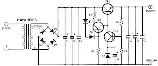
Component List
R1_____________1K
R2_____________470K
R3_____________330K
R4_____________20K
C1_____________39uF 450V
C2_____________39uF 450V
C3_____________39uF 450V
C4_____________39uF 450V
C5_____________10uF 25V
C6_____________220nF 250V
C7_____________100nF 400V
D1_____________1N4007
D2_____________1N4007
D3_____________1N4007
D4_____________1N4007
D5_____________1N4148D6_____________1N4148
TR1____________MJE13005
TR2____________MPSA92
TR3____________MPSA42
Wednesday, November 6, 2013
800W high power mosfet amplifier
This amplifier can be used for practically any application that requires high power, low noise, distortion and excellent sound. Examples would be Sub-woofer amp, FOH stage amplifier, One channel of a very high-powered surround sound amplifier etc.
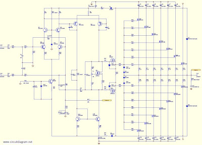
For detail explanation about how this circuit works include the large schematic diagram, power supply schematic diagram and complete component listing, link download this complete article.
Thursday, October 31, 2013
High power car audio amplifier
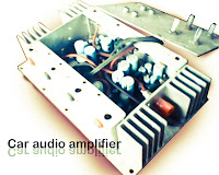 This is a power amplifier which functioned as the car audio amplifier IC that uses PA02 and LH0101. That each IC has a 30W output power with 8 ohm impedance.
Part List
R1 = 10K
R2 = 0.15R
R3 = 20K
R4 = 2.7R 1W
R6 = 15R
R7 = 10K
C1 = 0.1uF
C2 = 0.1uFC3 = 0.1uF
IC = LH0101 , PA02
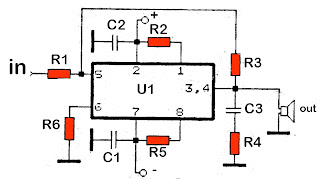
Supply voltage from 7 volts to 25 volts. For a car battery can also be used but must be first converted into voltage +, -, and ground. Following a series of amplifier.
Saturday, October 19, 2013
300W High Power Amplifier
This high power amplifier circuit with transistor was designed to provide a manipulate in lieu of the otherwise useless TO3 power transistors with the purpose of many hobbyists experience at home their throw out megabucks. With upright construction the module is gifted of tall quality performance and is rated to 300 watts into a 4 ohm load depending on power supply. With the driver and output transistors specified it is some degree of to DC rails of +/- 70 volts.
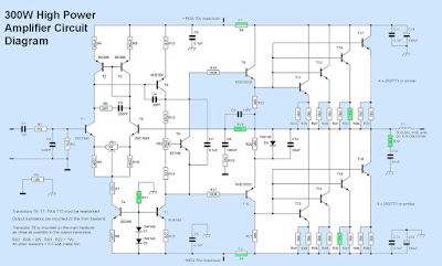 |
| Circuit Diagram |
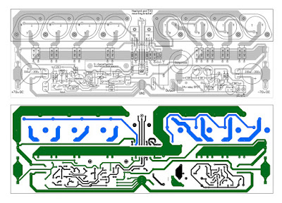 |
| 300W High Power Amplifier PCB layout |
Wednesday, October 16, 2013
High and quality audio power amplifier with MJ15024G and MJ15025G
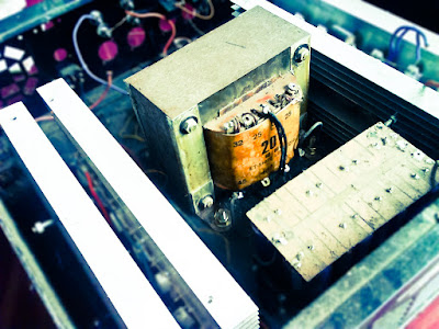
Spesification of this amplifier is high enough , and require a lot of expense to make this super-power amplifier. In the transformer using 20A and manufactered / branded ERA , ERA trafo is one of the best transformer , in addition to the power amplifier as well as power supply adapter , regulator , stabilizer , charger , etc. Because copper is intact , a strong iron and did not issue a frequency so that when the amplifier is turned on , output sound amplifier no buzzing. So if you in choosing a transformer , do not hesitate to use the transformer branded ERA.
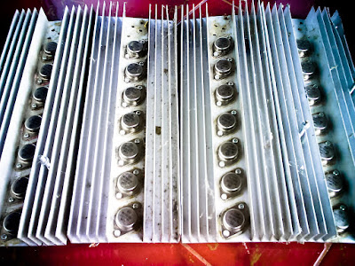
Above and below the picture is the end of the amplifier circuit, so-called booster amplifier. Picture above using 14 pairs of transistor MJ15025G and his partner MJ15024G . Transistor price range of $5 - $6 , has power output of 250W on each transistor , for more details , see datasheet of each transistor.
 |
| Click to view larger |
 |
| Installed transistor with resistor but still a mess |
Transistors MJ5025G and MJ15024G very fith with power amplifier 300 Watt subwoofer , 450 Watt , 600W , 750 Watt , 1050 Watt , 1200 Watt , and higher. The buffer and its driver using transistor not ic. For power schematic diagram can be found here.
Sunday, October 13, 2013
High Efficiency 12V White LED Driver
DC powered LED lighting circuits can vary from trivial single LED/series resistor combos to simple analog current regulators to more complicated switching power supply circuits such as this project. There is a tradeoff between simplicity and circuit capabilities. This more complex circuit adds features such as regulated light level across a wide range of input voltages and automatic circuit shutoff on low input voltage. By using a high frequency switching regulator, the power loss associated with the current dropping resistors found in simpler circuits is reduced. This offsets the power consumed by the circuits active parts. This circuit can power 10 white LEDs at 24mA of current with only 98mA of input supply current when running on 12V. LED intensity is fully regulated across the entire operating voltage range.
High Efficiency 12V White LED Driver Circuit Diagram
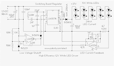
This circuit was inspired by F. Garcias IR LED video illumination circuit, published in the July 2001 edition of Nuts and Volts magazine. I modified the LED count and feedback circuit, and added the important low voltage shutdown feature.
Specifications:
The heart of the circuit is a string of 10 white LEDs. These are wired in series and connected to a current-regulated step-up switching power supply circuit.
The LM3578 switching regulator and its associated inductor, 1N5819 schottky diode, and 100uF 50V capacitor step the 12V power supply up to a higher DC voltage. The voltage is approximately 3.7 X the number of LEDs. The 4.7 ohm resistor on the cathode end of the LED string develops a voltage that is proportional to the current through the LEDs. This voltage is amplified by half of the LM358 op-amp and sends a negative feedback signal through a 4.7K resistor back to the LM3578. The 36K feedback resistor across the LM358 sets the LED series current to approximately 24mA. Not all general purpose op-amps will work in this circuit, the LM358 can operate from a single-rail power supply with both input pins near 0V.
The other half of the LM358 (pins 1,2,3) is wired as a 10V voltage comparator. The 1N5231 zener diode and 10K series resistor produces a steady 5V on pin 2 of the LM358. The two 100K resistors on pin 3 of the LM358 divide the input voltage in half. If the supply voltage drops below 10V, the output of the LM358 drops, and pulls pin 2 of the LM3578 down through a 1N5819 schottky diode, causing the LM3578 to shut down. A schottky diode is used instead of a standard silicon diode in order for the LM3578 pin 2 voltage to go low enough to disable the circuit. Without the low voltage shutdown circuit, the LM3578 current will increase as the supply voltage decreases until the IC self-destructs.
The 2.2M resistor across the LM358 produces a hysteresis effect for the low voltage shutoff. The circuit turns off about .25V below where it turns back on, this prevents oscillation around the shutoff threshold. Below the low voltage shutoff point, the circuit will consume about 5mA of current.
An interesting characteristic of this circuit is that it acts as a negative resistance at the power supply terminals. As the supply voltage is increased, the current will drop. The total power consumption stays nearly even across changing input voltage conditions.
Use:
Just connect the circuit to a 12V DC power supply, such as a solar charged lead acid battery. The light level will remain constant through the battery voltage change, and the circuit will consume a minimal amount of power.
It is possible to vary the number of white LEDs in this circuit from 8 to 12, as the LED count goes up, so does the regulators output voltage and input current. Numerous readers have asked me if this circuit can drive more than 12 3.7V white LEDs, 12 white LEDs is about the maximum upper power limit for the LM3578 IC. If you are driving lower voltage LEDs such as 1.4V IR or red parts, the series string can have up to 30 LEDs.
Parts:
1X LM3578AN switch-mode voltage regulator IC
1X LM358P dual op-amp
1X 1N5231 5V zener diode
2X 1N5819 schottky diodes
10X high intensity white LEDs
1X 100uF 25V electrolytic capacitor
1X 100uF 50V electrolytic capacitor
1X 100nF 50V ceramic or MLCC capacitors
1X 2nF 50V ceramic or MLCC capacitor
2X 1nF 50V ceramic or MLCC capacitors
1X 22pF ceramic disc capacitor
1X 0.3 ohm 1/4 W resistor (Substitutes: 3X 1 ohm or 2X 0.62 ohm 1/4W resistors in parallel)
1X 4.7 ohm 1/2W resistor
2X 4.7K 1/4W resistors
1X 10K 1/4W resistor
1X 36K 1/4W resistor
2X 100K 1/4W resistors
1X 220K 1/4W resistor
1X 2.2M 1/4W resistor
1X 1mH 200mA switching power supply inductor
Inductors that are known to work:
Mouser part 851-CDRH74NP-102MC (Sumida SMD)
Digi-Key part TKS3504CT-ND (Toko 875FU-102M=P3)
High Efficiency 12V White LED Driver Circuit Diagram
This circuit was inspired by F. Garcias IR LED video illumination circuit, published in the July 2001 edition of Nuts and Volts magazine. I modified the LED count and feedback circuit, and added the important low voltage shutdown feature.
Specifications:
- Power Requirements:
- Operating Voltage: 10-18V DC
- Operating Current: 98mA @ 12V DC (10 LEDs)
- Current at low voltage shutoff point: 5mA
The heart of the circuit is a string of 10 white LEDs. These are wired in series and connected to a current-regulated step-up switching power supply circuit.
The LM3578 switching regulator and its associated inductor, 1N5819 schottky diode, and 100uF 50V capacitor step the 12V power supply up to a higher DC voltage. The voltage is approximately 3.7 X the number of LEDs. The 4.7 ohm resistor on the cathode end of the LED string develops a voltage that is proportional to the current through the LEDs. This voltage is amplified by half of the LM358 op-amp and sends a negative feedback signal through a 4.7K resistor back to the LM3578. The 36K feedback resistor across the LM358 sets the LED series current to approximately 24mA. Not all general purpose op-amps will work in this circuit, the LM358 can operate from a single-rail power supply with both input pins near 0V.
The other half of the LM358 (pins 1,2,3) is wired as a 10V voltage comparator. The 1N5231 zener diode and 10K series resistor produces a steady 5V on pin 2 of the LM358. The two 100K resistors on pin 3 of the LM358 divide the input voltage in half. If the supply voltage drops below 10V, the output of the LM358 drops, and pulls pin 2 of the LM3578 down through a 1N5819 schottky diode, causing the LM3578 to shut down. A schottky diode is used instead of a standard silicon diode in order for the LM3578 pin 2 voltage to go low enough to disable the circuit. Without the low voltage shutdown circuit, the LM3578 current will increase as the supply voltage decreases until the IC self-destructs.
The 2.2M resistor across the LM358 produces a hysteresis effect for the low voltage shutoff. The circuit turns off about .25V below where it turns back on, this prevents oscillation around the shutoff threshold. Below the low voltage shutoff point, the circuit will consume about 5mA of current.
An interesting characteristic of this circuit is that it acts as a negative resistance at the power supply terminals. As the supply voltage is increased, the current will drop. The total power consumption stays nearly even across changing input voltage conditions.
Use:
Just connect the circuit to a 12V DC power supply, such as a solar charged lead acid battery. The light level will remain constant through the battery voltage change, and the circuit will consume a minimal amount of power.
It is possible to vary the number of white LEDs in this circuit from 8 to 12, as the LED count goes up, so does the regulators output voltage and input current. Numerous readers have asked me if this circuit can drive more than 12 3.7V white LEDs, 12 white LEDs is about the maximum upper power limit for the LM3578 IC. If you are driving lower voltage LEDs such as 1.4V IR or red parts, the series string can have up to 30 LEDs.
Parts:
1X LM3578AN switch-mode voltage regulator IC
1X LM358P dual op-amp
1X 1N5231 5V zener diode
2X 1N5819 schottky diodes
10X high intensity white LEDs
1X 100uF 25V electrolytic capacitor
1X 100uF 50V electrolytic capacitor
1X 100nF 50V ceramic or MLCC capacitors
1X 2nF 50V ceramic or MLCC capacitor
2X 1nF 50V ceramic or MLCC capacitors
1X 22pF ceramic disc capacitor
1X 0.3 ohm 1/4 W resistor (Substitutes: 3X 1 ohm or 2X 0.62 ohm 1/4W resistors in parallel)
1X 4.7 ohm 1/2W resistor
2X 4.7K 1/4W resistors
1X 10K 1/4W resistor
1X 36K 1/4W resistor
2X 100K 1/4W resistors
1X 220K 1/4W resistor
1X 2.2M 1/4W resistor
1X 1mH 200mA switching power supply inductor
Inductors that are known to work:
Mouser part 851-CDRH74NP-102MC (Sumida SMD)
Digi-Key part TKS3504CT-ND (Toko 875FU-102M=P3)
Wednesday, October 2, 2013
Powerful high quality amplifier
Nmos350 Mk2
This revised version yet to be built improves a few perfomance areas. I considered more complex ideas but this increased the component count and original idea of the amp would have been lost; that is a powerful high quality amplifier that used commonly available and cheap components.
- A LED as the voltage reference for the first stage constant current source tracks changes in temperature slightly better that than the old double diode setup.
- A cascode second stage makes it faster and more linear.
- Better clipping attributes
- The fuse has been shifted out of the voltage drive loop between the driver and output stages.

Nmos350 Mk2 Schematic
Subscribe to:
Posts (Atom)