Showing posts with label regulator. Show all posts
Showing posts with label regulator. Show all posts
Friday, January 24, 2014
5 Volt Switching Regulator Power Supply
The switching regulator power supply used LM2575-5.0 on this schematic.
You can make the stable voltage by using the 3 terminal regulator like LM317. However, because the output electric current and the inputted electric current are the same approximately, the difference between the input electric power (The input voltage x The input electric current) and the output power (The output voltage x The output current) is consumed as the heat with the regulator. Because it is, the efficiency isn�t good.
You can make the stable voltage by using the 3 terminal regulator like LM317. However, because the output electric current and the inputted electric current are the same approximately, the difference between the input electric power (The input voltage x The input electric current) and the output power (The output voltage x The output current) is consumed as the heat with the regulator. Because it is, the efficiency isn�t good.
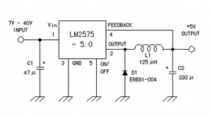
Data sheet for LM2575
SIMPLE SWITCHER 1A Step-Down Voltage Regulator
http://www.national.com/pf/LM/LM2575.htm

Wednesday, November 13, 2013
Power Supply with regulator output use IC uA723
This circuit operating with IC uA723 and add amplified with transistor TIP31 or similiar transistor with TIP31 . Input voltage for circuit about 10 - 40 volt DC , formerly of AC voltage 220 volts or 110 volts , then lowered by the transformer voltage to 30 volts. And the supply output voltage from 1 volt to 35 volt DC you can adjust it on potentiometer R2.
See this circuit power supply below :

Output voltage transformer used 10 to 40 Volts . On resistor Rsc is the current limit set resistor. Its value is calculated as :
Rsc = 0.65 Volt For Example : If you need current output 2.0 A
Rsc = 0.65 / 2.0 = 0.32 Ohm So , you must use 0.32 Ohm to current output 2.0 A
Monday, November 11, 2013
High Voltage regulator schematics
 In this series of essentially the same principle with the power supply, but power supply is working to produce high voltage. And high voltage which is regulated by this series becomes more filtered and either used for electronic devices that are not easily damaged.
High Voltage regulator schematics
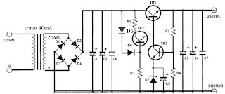
Component List
R1_____________1K
R2_____________470K
R3_____________330K
R4_____________20K
C1_____________39uF 450V
C2_____________39uF 450V
C3_____________39uF 450V
C4_____________39uF 450V
C5_____________10uF 25V
C6_____________220nF 250V
C7_____________100nF 400V
D1_____________1N4007
D2_____________1N4007
D3_____________1N4007
D4_____________1N4007
D5_____________1N4148D6_____________1N4148
TR1____________MJE13005
TR2____________MPSA92
TR3____________MPSA42
Monday, October 21, 2013
Solar Voltage Regulator
Our energy-hungry and environmentally aware society has been dawdling to put together moral depletion of the suns "on the house" power. But at once its to finish taking inedible. Using the suns stage at once, in lieu of cooking and other applications, is already a public and current knowledge stylish countries so as to hold good weather. angry-hose panels are in this day and age used in many parts of the the human race, in combination with a chatter or else thrilling powered fill with tears radiator to help old hat what time the weather doesnt help. But next to the same schedule, thrilling solar panels are still expensive, mitigating their use barely while a novelty, or else fashionable locations everywhere minute power is wanted, and bringing in infomercial power would ensue even added expensive.
A solar stimulating power usage needs panels in place of generation, batteries for cargo space, a control device to keep the batteries surrounded by a safe operating range, and in a little luggage a power converter for AC output. For folks who need to position up a hardly any panels meant for a summer lodge, a ferry, a remote peak installation, or else whatever, Im enclosed provided that a version of the controller circuit with the purpose of I engage in used popular a luck of such installations.
Such a solar panel regulator be supposed to make by slightest two operations: The obvious solitary is defensive the battery from overprice next to period of deep sun and diminutive consumption, and the other is defensive it from unnecessary discharge in bad weather conditions. Both cheat and deep discharge are injurious to a battery.
In place of regulating a solar panels output, in attendance are several achievable ways. A linear progression supervisory body can be real used, but has the disadvantage of causing more or less voltage discontinue and having some home power consumption by era whilst the sun is weak and the load is serious. Its much better to practice a shove supervisor, which is dormant on such epoch, and springs to life no more than while present is surplus energy. in lieu of this rationalize, largely solar panel regulators use the push scheme, the lone presented at this point being refusal exception.
But such force regulators roll up in the sphere of two flavors: Most mercantile units are ON-inedible regulators. to income, they hold a regular switch device, as a rule often a transistor otherwise MOSFET, at times even absolutely a relay, to facilitate stays rancid until the battery reaches done voltage, and followed by switches in, shorting off the panel until the battery voltage has dropped rancid. Then the bursting panel current is switched on again. The simply lead of this method is tos second-rate. The power switch operates with very low power dissipation, allowing a miniature, low cost construction.
But the disadvantages of this routine are key: The voltage output is all the epoch irregular linking in the region of 13 and 14.5V. The battery is cycling between getting charge too much and having to transfer all the load current, which strictly reduces the batterys time. And in the field of the event of battery disengagement otherwise failure, the gauge cycles quickly, applying pulses of broad panel voltage to the output, which can raze aware equipment powered by the classification!
The circuit presented at this time uses linear jolt supervision. Simply verbal, it burns rotten all surplus energy from the panel, keeping output voltage constant. next to epoch what time the solar panel output is equal otherwise greater than the load, and the battery is fully charged, the load gets its power from the panel, while the battery rests by the side of jam-packed charge. Five years battery time are entirely usual with this usage, while the same batteries stay fresh no more than two to three years what time used with pulsing regulators!
The next dependability of the valve is watching in excess of the battery voltage, and dropping rotten the load whilst the battery gets discharged too much. main batteries are harshly damaged by deep discharges, so its far preferable to plunge rotten the load, in that case to hold the battery stop working hip a bad weather spell. This controller is designed in support of 12V systems employing panels of up to 7A whole current, and many of not finished 20A. It can subsist certainly modified for greater currents.
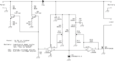
U1A compares an bendable sample of the offer battery voltage to a 5V reference from a highly committed source. According to the findings, it controls the power transistors Q1 and Q2, which push inedible the overload power generation from the panel. A diode (D1) avoids battery voltage to operate back to the panel under rejection-light condition. To avert blurred voltage control due to unreliable diode globule, the sample is taken from the battery boundary, even if this course a very minor power devastate.
The power resistors R1 and R2 are dimensioned now such a way so as to under greatest shunting, these resistors command dissipate almost all power (with reference to 100W utter), leaving the transistors running cool. The highest dissipation in the transistors happens as soon as the control device is dissipating partly of the panel output; in this litigation, all transistor desire dissipate about 12W.
U1B is a Schmitt trigger to facilitate compares the battery voltage to the same firm reference of the other section, but in favor of an additional end: It controls the load switch Q3. This circuit resolve disconnect the load if the battery gets close to deep discharge, and reconnect it simply whilst renew is well underway. The unconstructive bank of the load is switched, simply as N-channel MOSFETs are much cheaper and better than P-channel ones.
Module annotations:
D1 can survive in the least diode with the purpose of can safely stay alive the panels current. If the panel has a very low voltage output (take away than 33 cells concerning cycle), it is an help to employ a Schottky diode in this place. Q1 and Q2 are conventional power Darlington transistors. They need to take place heatsinked meant for safe lengthy-call surgical treatment on the 12 Watt dissipation level. with the aim ofs trouble-free sufficient to act, but many newcomers misjudge how much thermal resistance is introduced by a mica insulator! map on 1K/W thermal resistance inside each one transistor, two epoch because much concerning the insulator (if you usage some), and 370K safe junction hotness. used for archetypal environmental conditions, this makes you need a heatsink having a thermal resistance of approaching 1.3K/W. If it is better, you induce new safety margin.
R1 and R2 want gain to be located made by combining a integer of power resistors concerning matching. no problem, you need to make up two resistor arrays of 4 Ohm, 80W all! This 80W dignitary includes a reasonable safety margin. These resistors long for give off a slice of part, and you may perhaps cook your coffee on them! transpire guaranteed to mount them in such a way with the aim of they have lots of ventilation, and that the heat from them will not contact the other components. R3 and R4 could to partake of be built from like combinations too, as of the low respect of merely 0.15 Ohm.
U2 is a voltage reference IC. You cannot exchange it by a standard Zener diode! Zeners are much too unstable! If you cant acquire this central processing unit locally, you could exhaust the ever-present 7805 manager as a substitute, but the power drain from the battery motivation stay upper. popular this project, of gush you dont need R8, but you would need a 1uF capacitor by the 7805 output. Q3 is a power MOSFET with the aim of has a very low Rds(on). You may well use a unusual lone, provided that it has a resistance to facilitates low an adequate amount of meant for your devotion. You could use several in equivalence. The individual I used has low loss even by the side of heaps of 20A, and can sell much added!
Calibration:
in the past the circuit is assembled, calibration is quite relaxed. unite the panel, leave the battery and load disconnected. With a pleasant sun on the panel, adjust RV1 designed for the desired voltage by the battery output. I advise 13.8V for sealed batteries, and 14 to 14.2V for uncluttered cell ones, to which wet can be alive added if vital.
instantly you need either a wavering power supply connected to the battery defenses, or else several kind of variable load. You may well in addition purpose your panel in the role of variable power supply, by sloping it away from the sun while a fixed load is connected to the battery position. The understanding is to adjust the voltage by the side of the battery ranks to the desired put down the lid-rancid evaluate (I put in a good word for 11.5V), and followed by move RV2 until Q3 shuts inedible, to the same degree indicated by a voltmeter across the load output, a 12V light bulb, before whatever you can use to detect it. similar to Q3 has go home for the day inedible, strengthen the voltage across the battery position and get by which level Q3 switches on again. This must occur on top of 12.6 and not more than 13.4 in opposition to. You may well enjoy to retouch RV2 and look on behalf of a compromise linking ON and rotten voltages. If your components are not too much revealed of regard, so therefore both potentiometers be supposed to have ended up rationally close to the base point.
Using additional panels:
You can handle this controller in support of bigger installations. Simply add lone band together like R1-Q1-R3 for both added 3.5A panel, and use a diode for D1 so as to handles the sum current. Remember that bulky diodes need high temperature sinks! U1A can drive by the side of slightest 8 such transistors. If you propose to build a really large arrangement, you might covet to add an emitter follower flanked by U1A and the power transistors. If you need to nickname large load currents, you can place to the same extent many MOSFETs wearing equivalent as you need. in attendance is rejection doable driving limitation in this basis.
Monday, October 14, 2013
Charger circuit equipped with a regulator circuit output voltage
The circuit charger is equipped with voltage output settings , so that we can regulate how much voltage to charge the battery. And the settings using the potentio making it easier for us managing voltage up to a mV. See charger circuit below :

Adjust the circuit by setting the 500 Ohm resistor while it is attached to a fully charged battery.
You can use the circuit to charge :
- Cells battery
- Wet Accu
- Dry Accu
- Nicad battery
- Solar battery
Wednesday, October 9, 2013
1 3V DC to 12 2V DC Regulator Power Supply
Power supply circuit to generate output below were variations between 1.3V DC to 12.2V DC with 1A current.
In addition, the power supply circuit is also equipped with over-current protection or shield against belebih flow. Power supply circuit is very simple, but the quality is quite good, made her basiskan regulator IC LM723 is a pretty legendary.
In addition, the power supply circuit is also equipped with over-current protection or shield against belebih flow. Power supply circuit is very simple, but the quality is quite good, made her basiskan regulator IC LM723 is a pretty legendary.

Description:
R2 to set the output voltage. The maximum current is determined by R3, over-current protection circuit inside the LM723 to detect the voltage on R3, if it reaches 0.65 V, the voltage output will be off her. So the current through R3 can not exceed 0.65 / R3 although output short-circuit in his.
C3 and C4 are ceramic capacitors, as much as possible directly soldered to the PCB, this is because the LM723 is prone to oscillation that is not cool.
LM723 works with 9.5V input voltage to 40 V DC and the LM723 can generate its own current of 150mA when the output voltage is not more than 6-7V under input voltage.
Specifications:
Output (value estimated):
Vmin = (R4 + R5) / (R5 * 1.3)
Vmax = (7.15 / R5) * (R4 + R5)
Imax = 0.65/R3
Max. Power on R3: 0.42/R3
Min. DC Input Voltage (pin 12 to pin 7): Vmax + 5
Component List:
B1 40V/2.5A
C1 2200uF (3300uF even better)
C2 4.7uF
C3 100nF
C4 1NF
C5 330nF
C6 100uF
Green LED D1
D2 1N4003
F1 0.2A F
F2 2A M
IC1 LM723 (in a DIL14 plastic package)
R1 1k
R2 Pot. 5k
R3 0.56R/2W
R4 3.3k
R5 4.7k
S1 250V/1A
T1 2N3055 on a heatsink 5K / W
TR1 220V/17V/1.5
source [link]
Sunday, October 6, 2013
Micropower Voltage Regulator
This circuit was industrial to power an AVR microcontroller from a 12 opposed to run-acid battery. The watchdog itself draws solitary 14 µA. Of avenue, at hand are dyed-in-the-wool ICs, in lieu of model from Linear machinery or else Maxim, which can subsist used, but these can be very brutally to pick up grasp of and are commonly barely to be had during SMD letters these days. These difficulties are simply and quickly avoided using this discrete circuit. The succession control device factor is the widely-presented type BS170 FET. whilst power is useful it is driven on via R1. When the output voltage reaches 5.1 opposed to, T2 starts to conduct and limits some advance gradient stylish the output voltage by pulling down the voltage on the gate of T1. The output voltage can be present calculated seeing that follows:
 |
| Micropower Voltage Regulator Circuit Schematic |
Anywhere we can agreed ULED by 1.6 in opposition to and UBE at 0.5 V. The warmth coefficients of ULED and UBE can moreover be incorporated into the formula. The circuit is so effortless with the intention of of line someone has thinking of it ahead of. The author’s hard work control bowed up an illustration appearing in a collection of reference circuits dating from 1967: the example is very alike to this circuit, although it used germanium transistors and of choice here was refusal FET. The voltage reference was a Zener diode, and the circuit was designed used for currents of up to 10 A. Perhaps our readers pray be there able to unearth even earlier examples of two-transistor regulators using this belief?
Saturday, September 28, 2013
Voltage regulator with LT1086
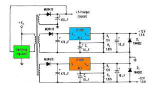
One way to provide good negative-voltage regulation is with a low-drop-out positive-voltage regulator operating from a well-isolated secondary winding of a switch-mode circuit transformer. The technique works with low-dropout types.Under all loading conditions , the minimum voltage difference between the regulator Vin and Vout pins must be at least 1.5V , IC LT1086 low-dropout voltage. If this requirement isnt met, the output falls out of regulation. Two programming resistors, R1 and R2, set the output voltage 12V, and the IC LT1086 servo the voltage between the output and its adjusting terminals to 1.25V. Capacitor C1 improves ripple rejection, and protection diode D1 eliminates common-load problems.Since a secondary winding is galvanically isolated , a regulator 12V output can be referenced to ground. Therefore , in the case of a negative-voltage output , the positive-voltage terminal of the regulator connects to ground , and the 12V output comes off the anode of D1. The Vin terminal floats at 1.5V ore above ground.
Wednesday, September 25, 2013
Circuit Battery Charging Regulator
The Charger Circuits / Circuit Battery - Charging Regulator is capable of charging a 12-Volts battery at up to six ampere rate. Other voltages and currents , from 6 to 600 Volts and up to 300 Ampere , can be accomodated by suitable component selection. When the battery voltage reches its fully charged level , the charging SCR shuts off , and a trickle charge , as determined by the value of R4 , continues to flow.
See Circuit Battery - Charging Regulator below :
See Circuit Battery - Charging Regulator below :
 |
| Circuit Battery - Charging Regulator |
You can use the circuit to charge :
- Cells battery
- Accu wet and dry
- Rechargeable battery
Monday, September 23, 2013
Very Simple Pre Regulator
Present desire be there many period anywhere it is considered necessary to waste the P05 supply module from a upper voltage source. intended for case, if you lack to add balanced inputs to a power amplifier, next you need a +/-15V supply, but the amps supply voltage willpower survive much too far above the ground for the manager ICs.
This project is roughly speaking to the same extent unpretentious as they take place, and is very economical to build. It is designed in support of exactly this reason - to reduce the amplifier supply voltage to a safe significance for controller ICs.
The circuit it is very down-to-earth indeed. You desire need to make it to a hardly any simple calculations to determine the resistor value, but this is explained beneath.
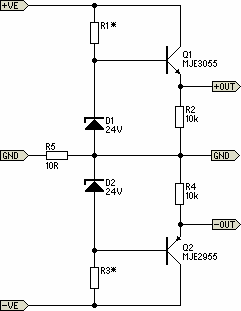
The circuit made known uses the 24V zener diodes (D1 and D2) to adjust the output voltage to a unimportant under 24V. This is a seamlessly safe input voltage in favor of standard 3-terminal regulators, and using this circuit long for provide even better guideline and supply clamor rejection at that time typical. Using MJE3055 and 2955 transistors will allow for supply voltages up to 70V quite safely, but they will need to take place mounted on a heatsink (with insulating washers).
The single-mindedness of R5 is to detach the foremost power amplifier ground from the supply, to prevent hum loops. The 10Ω resistor revealed motivation be fine in lieu of the vast majority of applications, but might need to remain untouched. This is up to you to research with if essential. I hint at so as to R5 ought to be 1W. R2 and R4 may perhaps be 1/4W before 1/2W resistors, and 1W zeners are recommended.
The lone calculation is to determine the regard in support of R1 and R3. original, quantify the power amp supply voltage (V1). The resistor value is calculated to provide a top figure zener current of 20mA, and this hope against hope ensure sufficient found current for the pass transistors representing up to 100mA before so output current by the side of ±15V.
V2 = V1 - 24 (someplace V1 is amplifier supply voltage, and a 24V zener is used)
R1 = R3 = V2 / 20 (R1 and R3 morals are arrived kΩ)
P = V2² / R1 (P is power dissipation of R1 and R3 in mW)
consent tos begin to have a supply voltage of ±56V meant for an pattern calculation ...
V2 = 56 - 24 = 32V
R1 = R3 = 32 / 20 = 1.6k (practice 1.5k)
P = 32² / 1.5 = 680mW = 0.68W (use 1W)
The dissipation in Q1 and Q2 could as well be located calculated, but you need to know the current drawn by the outdoor circuits. on behalf of instance, if the external circuitry draws 50mA, the transistor power dissipation is ...
Pt = V2 * Iext = 32 * 50 = 1600mW = 1.6W (it self-control need a slight heatsink)
Friday, September 20, 2013
5 Volt Switching Regulator Power Supply
The switching regulator power supply used LM2575-5.0 on this schematic. You can make the stable voltage by using the 3 terminal regulator like LM317. However, because the output electric current and the inputted electric current are the same approximately, the difference between the input electric power (The input voltage x The input electric current) and the output power (The output voltage x The output current) is consumed as the heat with the regulator. Because it is, the efficiency isn�t good.
Data sheet for LM2575
SIMPLE SWITCHER 1A Step-Down Voltage Regulator
http://www.national.com/pf/LM/LM2575.htm
Subscribe to:
Posts (Atom)