Showing posts with label dc. Show all posts
Showing posts with label dc. Show all posts
Friday, January 10, 2014
DC Servo Motor Controller
As we presented in another article the A3952S integrated circuit ( designed by Allegro MicroSystems ) can be used to design very simple and useful motor driver circuits . In the precedent article was presented a simple bipolar stepper motor driver circuit that use two A3952S circuits. As we presented in that article , the A3952S is capable of continuous output currents up to 2 A and operating voltages range up to 50 V.
DC Servo Motor Controller Circuit diagram

Warning , the 50 operating voltage is to power the motor , for the logic controller you will need a 5 volts Dc power supply .
This circuit presents a simple DC servo motor application that can be used in various electronic projects . As you can see in the circuit schematic this Dc servo motor driver schematic circuit use just one integrated circuit and other few external electronic components . With bidirectional dc servo motors, the PHASE terminal can be used for mechanical direction control. Similar to when braking the motor dynamically, abrupt changes in the direction of a rotating motor produce a current generated by the back EMF. The current generated will depend on the mode of operation.
DC Servo Motor Controller Circuit diagram
This circuit presents a simple DC servo motor application that can be used in various electronic projects . As you can see in the circuit schematic this Dc servo motor driver schematic circuit use just one integrated circuit and other few external electronic components . With bidirectional dc servo motors, the PHASE terminal can be used for mechanical direction control. Similar to when braking the motor dynamically, abrupt changes in the direction of a rotating motor produce a current generated by the back EMF. The current generated will depend on the mode of operation.
Monday, November 18, 2013
DC DC Converter 12V to 24V
This simple circuit is a DC-DC converter that converting up 12V source to a 24V. It can be used to run radios, small lights, relays, horns and other 24V accessories from a 12V vehicle with a maximum draw of about 800mA.
This DC-DC Converter can be used to charge one 12V battery from another, or step up the voltage just enough to provide necessary overhead for a 12V linear regulator. Using one op-amp as a squarewave oscillator to ring an inductor and another op-amp in a feedback loop, it wont drift around under varying loads, providing a stable 24V source for many applications. With a wide adjustment in output this circuit has many uses.
Parts List
R1-R4,R7-R8 100K 1/4W Resistor
R5 470 Ohm 1/2W Resistor
R6 10K Linear Pot
C1 0.01uF Mylar Capacitor
C2 0.1uF Ceramic Disc Capacitor
C3 470uF 63V Electrolytic Capacitor
D1 1N4004 Rectifier Diode
D2 BY229-400 Fast Recovery Diode See Notes
Q1 BC337 NPN Power Transistor
U1 LM358 Dual Op Amp IC
L1 See Notes
MISC Board, Wire, Socket For U1, Case, Knob For R6, Heatsink for Q1
DC- DC Converter Notes
1. R6 sets the output voltage. This can be calculated by Vout = 12 x (R8/(R8+R7)) x (R6B/R6A).
2. L1 is made by winding 60 turns of 0.63MM magnet wire on a toroidial core measuring 15MM (OD) by 8MM (ID) by 6MM (H).
3. D2 can be any fast recovery diode rated at greater then 100V at 5A. It is very important that the diode be fast recovery and not a standard rectifier. 4. Q1 will need a heatsink.
12V to 30V DC to DC Converter Schematic
12V to +/- 30V DC to DC Converter Circuit Diagram

This is a DC to DC converter for car power amplifier. 12V input generates +30V and -30V output for preamp or power amplifiers. Circuit uses SG3525 IC, Mosfets and switching power supply.
Saturday, November 16, 2013
L6203 DC Motor Controller
This DC motor controller circuit shown in this schematic use the L620x motor driver . The L620x is a monolithic full bridge switching motor driver realized in the new Multipower-BCD technology which allows the integration of multiple, isolated DMOS power transistors plus mixed CMOS/bipolar control circuits and is available in many versions : L6201 /1PS/2/3 .
L6203 DC Motor Controller Schematic

All this motor driver circuits are identically , the differences between them is the total RMS current , which is up to : 1A for L6201 , 2A for L6202 and 4A for L6203 and L6201PS . If the device is combined with a current regulator like the L6506 , can be implemented a transconductance amplifier for speed control, as shown in this circuit schematic . In this configuration only half of the L6506 is used and the other half of the device may be used to control a second motor.
The L6506 senses the voltage across the sense resistor RS to monitor the motor current: it compares the sensed voltage both to control the speed and during the brake of the motor. A snubber network made by the series of R and C must be foreseen very near to the output pins of the I.C.
The following formulas can be used to calculate the snubber values:
R @ VS/lp ; C = lp/(dV/dt) where:
VS is the maximum Supply Voltage foreseen on the application; Ip is the peak of the load current; dv/dt is the limited rise time of the output voltage (200V/ms is generally used).
of the IC. Sometimes a capacitor at pin 17 of the L6506 let the application better work.
L6203 DC Motor Controller Schematic
The L6506 senses the voltage across the sense resistor RS to monitor the motor current: it compares the sensed voltage both to control the speed and during the brake of the motor. A snubber network made by the series of R and C must be foreseen very near to the output pins of the I.C.
The following formulas can be used to calculate the snubber values:
R @ VS/lp ; C = lp/(dV/dt) where:
VS is the maximum Supply Voltage foreseen on the application; Ip is the peak of the load current; dv/dt is the limited rise time of the output voltage (200V/ms is generally used).
of the IC. Sometimes a capacitor at pin 17 of the L6506 let the application better work.
Sunday, November 3, 2013
DC motor driver with H Bridge IC L293D
Making a DC motor driver with H-Bridge technique can use IC L293D as in the article "DC Motor Driver H-Bridge L293 (2 Motor DC)"is. DC motor driver L293D can be used to control the DC motor 2 pieces at once. DC Motor Driver L293D can be used to control a DC motor continuously or with a PWM technique. Dc motor driver circuit in the article "DC Motor Driver H-Bridge L293 (2 Motor DC)" only use IC L293D only. For more details see the following figure.
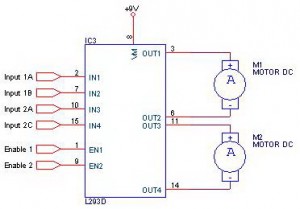
Working system of DC motor driver L293D is to provide control signals in the form of logic or pulse to the input lines 1A - 1B for DC motor control M1 and the input 2A - 2B for the control of DC motor M2 with the following conditions:
Input A Input B Motor DC0 0 Motor silent
1 0 motor rotates counterclockwise
0 1 Motor berputer clockwise
1 1 Motor silent
Description: Enable Input given a logic 1 to obtain such data in the table above.
Friday, November 1, 2013
555 Timer for DC to DC Converter Circuit
 |
| 555 Timer for DC to DC Converter |
This circuit is called DC TO DC converter circuit.Which increase the voltage circuit.There can be customized to change the output values. When the power supply input to IC1 is the output pin 3 at a frequency of 1 kHz.The frequency is Q1 and Q2, which will continue to use push pool work interchangeably.If this is the positive output signal Q1 Q2 will run the delete function this reason, C2 and C3 capacitors are half-wave alternating.When to use. Voltage from C2 to C3 is discharged out to the input voltage over almost two times less than 2 times due to the loss of diodes D1-D3.
Thursday, October 24, 2013
Simple Operational Amplifier DC Motor Driver
Using a simple operational amplifier and some other common electronic components can be designed a very simple DC motor driver that can be used for a 200mA motor application . Rb sets the bias point for transistors Q1 and Q2.

Because Vbe(ON) varies greatly with temperature, a guardband is required to prevent Q1 and Q2 from conducting simultaneously. RB should be selected such that the transistors do not conduct until lM equals the op amp quiescent supply current, Isy . The transistors will begin to conduct at about Vbe (on) = 0.5V. In this project :
RB= [vbe(on)/(lSY+ Im)]= 0.5/(0.0025 + 0.0025)=100 ohms
To maximize voltage swing across the motor, V1 must be minimized. If at full load V1 = 0.2V with V+ = 15V and VBE1 = 0.8V, the voltage across the motor will be:
VM = (V+ - 2) - VBE1 - V1 = (15 - 2) - 0.8 - 0.2 = 12.0V Vin may be scaled with a resistive divider as:
VIN= (R1 + R2)/R2 With R1 = 240k and R2 = 10k, VIN =5 volt lM = 200mA.
Wednesday, October 9, 2013
1 3V DC to 12 2V DC Regulator Power Supply
Power supply circuit to generate output below were variations between 1.3V DC to 12.2V DC with 1A current.
In addition, the power supply circuit is also equipped with over-current protection or shield against belebih flow. Power supply circuit is very simple, but the quality is quite good, made her basiskan regulator IC LM723 is a pretty legendary.
In addition, the power supply circuit is also equipped with over-current protection or shield against belebih flow. Power supply circuit is very simple, but the quality is quite good, made her basiskan regulator IC LM723 is a pretty legendary.

Description:
R2 to set the output voltage. The maximum current is determined by R3, over-current protection circuit inside the LM723 to detect the voltage on R3, if it reaches 0.65 V, the voltage output will be off her. So the current through R3 can not exceed 0.65 / R3 although output short-circuit in his.
C3 and C4 are ceramic capacitors, as much as possible directly soldered to the PCB, this is because the LM723 is prone to oscillation that is not cool.
LM723 works with 9.5V input voltage to 40 V DC and the LM723 can generate its own current of 150mA when the output voltage is not more than 6-7V under input voltage.
Specifications:
Output (value estimated):
Vmin = (R4 + R5) / (R5 * 1.3)
Vmax = (7.15 / R5) * (R4 + R5)
Imax = 0.65/R3
Max. Power on R3: 0.42/R3
Min. DC Input Voltage (pin 12 to pin 7): Vmax + 5
Component List:
B1 40V/2.5A
C1 2200uF (3300uF even better)
C2 4.7uF
C3 100nF
C4 1NF
C5 330nF
C6 100uF
Green LED D1
D2 1N4003
F1 0.2A F
F2 2A M
IC1 LM723 (in a DIL14 plastic package)
R1 1k
R2 Pot. 5k
R3 0.56R/2W
R4 3.3k
R5 4.7k
S1 250V/1A
T1 2N3055 on a heatsink 5K / W
TR1 220V/17V/1.5
source [link]
Saturday, October 5, 2013
DC to AC Inverter with IC CD4047
This DC to AC inverter circuit work based on unstable multi vibrator does. In this circuit, IC CD4047 is chosen as a heart of unstable multivibrator, because this IC type gives a complementary output that has opposite phase to another ( pin 10 and 11 as seen in Figure 1), and has 50 % duty cycle that satisfy to generate a pulse for inverter.
DC to AC Inverter with IC CD4047 Circuit Diagram

DC to AC Inverter with IC CD4047 Circuit Diagram
Saturday, September 28, 2013
TDA7275A DC Speed Controller
Using the TDA7275A linear integrated circuit manufactured in a minidip plastic package can be designed a very simple speed regulator electronic project that can be used for speed regulation of small DC motors .

TDA7275A DC speed controller project is intended for use as speed regulator for DC motors of record players, tape and cassette recorders. This DC motor speed controller circuit project can provide a maximum output current of 1.5 amperes .
This circuit can be powered with a voltage range between 8 and 18 volts . V2 is typically 1.5 volt for Motor ”Run” (Acc. Following data or open) and 1 volt for Motor ”Stop” (Acc. Following data or grounded) .
TDA7275A DC Speed Controller Schematic
This circuit can be powered with a voltage range between 8 and 18 volts . V2 is typically 1.5 volt for Motor ”Run” (Acc. Following data or open) and 1 volt for Motor ”Stop” (Acc. Following data or grounded) .
Subscribe to:
Posts (Atom)