Showing posts with label controller. Show all posts
Showing posts with label controller. Show all posts
Friday, January 10, 2014
DC Servo Motor Controller
As we presented in another article the A3952S integrated circuit ( designed by Allegro MicroSystems ) can be used to design very simple and useful motor driver circuits . In the precedent article was presented a simple bipolar stepper motor driver circuit that use two A3952S circuits. As we presented in that article , the A3952S is capable of continuous output currents up to 2 A and operating voltages range up to 50 V.
DC Servo Motor Controller Circuit diagram

Warning , the 50 operating voltage is to power the motor , for the logic controller you will need a 5 volts Dc power supply .
This circuit presents a simple DC servo motor application that can be used in various electronic projects . As you can see in the circuit schematic this Dc servo motor driver schematic circuit use just one integrated circuit and other few external electronic components . With bidirectional dc servo motors, the PHASE terminal can be used for mechanical direction control. Similar to when braking the motor dynamically, abrupt changes in the direction of a rotating motor produce a current generated by the back EMF. The current generated will depend on the mode of operation.
DC Servo Motor Controller Circuit diagram
This circuit presents a simple DC servo motor application that can be used in various electronic projects . As you can see in the circuit schematic this Dc servo motor driver schematic circuit use just one integrated circuit and other few external electronic components . With bidirectional dc servo motors, the PHASE terminal can be used for mechanical direction control. Similar to when braking the motor dynamically, abrupt changes in the direction of a rotating motor produce a current generated by the back EMF. The current generated will depend on the mode of operation.
Wednesday, December 25, 2013
L297 Stepper Motor Controller Circuits
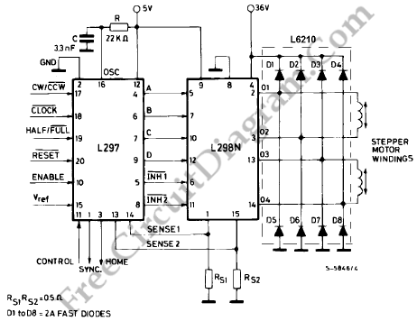 L297 Stepper Motor Controller Circuits
Four appearance drive signals for two appearance bipolar and four appearance unipolar footfall motors in microcomputer-controlled appliance is calmly implemented application L29 Stepper Motor Controller IC. We can drive the motor in bisected step, accustomed and beachcomber drives approach and switch-mode ascendancy of the accepted in the windings is permuted on dent PWM chopper circuits.
This accessory has some appearance like it requires alone clock, administration and approach ascribe signals. Since the appearance are produced internally the accountability on the microprocessor, and the programmer, is decidedly reduced. This accessory is army in DIP20 and SO20 packages. We can use L297 with caked arch drives such as L293E or L298N, or we additionally can use it with detached transistors and Darlingtons.
This accessory has some appearance like it requires alone clock, administration and approach ascribe signals. Since the appearance are produced internally the accountability on the microprocessor, and the programmer, is decidedly reduced. This accessory is army in DIP20 and SO20 packages. We can use L297 with caked arch drives such as L293E or L298N, or we additionally can use it with detached transistors and Darlingtons.
Saturday, December 21, 2013
Automatic Water Pump Controller Circuit
Automatic water pump controller is a series of functions to control the Automatic Water Pump Controller Circuit in a reservoir or water storage. As the water level sensor made with a metal plate mounted on the reservoir or water tank, with a sensor in the short to create the top level and a detection sensor for detecting long again made the lower level and ground lines connected to the bottom of reservoirs or reservoir. The series of automatic water pump controller is designed with 2 inputs NOR by 4 pieces and relay that is activated by the transistor. Automatic water pump circuit requires +12 VDC voltage source and can be used to control the water pump is connected to AC power . Here is the complete series of pictures.
Series Automatic Water Pump Controller

List Component Automatic Water Pump Controller
R1 = 15K
R2 = 15K
R3 = 10K
R4 = 1K
D1 = LED
D2 = 1N4148
Q1 = BC337
IC1 = 4001
SW = SPDT Switches
Relay RL1 = 12V
The working principle series of automatic water pump controller above is. At the time the water level is below both sensors, the output IC1C (pin 10) will be LOW, Kemudin when the water began to touch the lower level sensor, the output IC1C (pin10) remains LOW until the water touches the sensor level above, then the output IC1C (pin 10) going HIGH and active relay through Q1 and turn on the water pump to meguras reservoir. At the muli down and water level sensors for water untouched MKA IC1C output (pin 10) remains HIGH until the new water untouched semuasensor IC1C output (pin 10) LOW and water pump died. The series of automatic water pump controller is equipped with SW1 which serves to reverse the logic of drains (the output of IC1C) and the concept of water supplied (output dri IC1D). When SW1 is connected to IC1D the water pump will turn on when the water does not touch all the sensors and will die when all the sensors tesentuh water. Automatic water pump controller can be used to fill or drain the water according to which mode is selected via SW1.
Friday, December 20, 2013
LMD18200 Motor Controller Schematic
Using the LMD18200 3A H-Bridge designed by National Semiconductors for motion control applications can be designed a very simple motor controller electronic project . Ideal for driving DC and stepper motors; the LMD18200 accommodates peak output currents up to 6A. An innovative circuit which facilitates low-loss sensing of the output current has been implemented.
LMD18200 Motor Controller Schematic

This circuit controls the current through the motor by applying an average voltage equal to zero to the motor terminals for a fixed period of time, whenever the current through the motor exceeds the commanded current. This action causes the motor current to vary slightly about an externally controlled average level. The duration of the Off-period is adjusted by the resistor and capacitor combination of the LM555.
Using this motor driver circuit you can design a 24 DC motor that require a maximum current consumption of 3 amperes .
LMD18200 Motor Controller Schematic
Using this motor driver circuit you can design a 24 DC motor that require a maximum current consumption of 3 amperes .
Saturday, November 16, 2013
L6203 DC Motor Controller
This DC motor controller circuit shown in this schematic use the L620x motor driver . The L620x is a monolithic full bridge switching motor driver realized in the new Multipower-BCD technology which allows the integration of multiple, isolated DMOS power transistors plus mixed CMOS/bipolar control circuits and is available in many versions : L6201 /1PS/2/3 .
L6203 DC Motor Controller Schematic

All this motor driver circuits are identically , the differences between them is the total RMS current , which is up to : 1A for L6201 , 2A for L6202 and 4A for L6203 and L6201PS . If the device is combined with a current regulator like the L6506 , can be implemented a transconductance amplifier for speed control, as shown in this circuit schematic . In this configuration only half of the L6506 is used and the other half of the device may be used to control a second motor.
The L6506 senses the voltage across the sense resistor RS to monitor the motor current: it compares the sensed voltage both to control the speed and during the brake of the motor. A snubber network made by the series of R and C must be foreseen very near to the output pins of the I.C.
The following formulas can be used to calculate the snubber values:
R @ VS/lp ; C = lp/(dV/dt) where:
VS is the maximum Supply Voltage foreseen on the application; Ip is the peak of the load current; dv/dt is the limited rise time of the output voltage (200V/ms is generally used).
of the IC. Sometimes a capacitor at pin 17 of the L6506 let the application better work.
L6203 DC Motor Controller Schematic
The L6506 senses the voltage across the sense resistor RS to monitor the motor current: it compares the sensed voltage both to control the speed and during the brake of the motor. A snubber network made by the series of R and C must be foreseen very near to the output pins of the I.C.
The following formulas can be used to calculate the snubber values:
R @ VS/lp ; C = lp/(dV/dt) where:
VS is the maximum Supply Voltage foreseen on the application; Ip is the peak of the load current; dv/dt is the limited rise time of the output voltage (200V/ms is generally used).
of the IC. Sometimes a capacitor at pin 17 of the L6506 let the application better work.
Tuesday, November 12, 2013
PWM controller with 555 timer chip

IC Timer 555 has a basic PWM controller with pulse width control feature 0 .. 100% which is controlled using the R1, at the time of controlling the oscillator frequency relatively stabi so it may be used to build the Simple PWM controller.
Frequency of Simple PWM controller 555 depending on the value of R1 and C1, values shown R1 and C1 will form the output with a frequency of 170 to 200 Hz. Diode-diode used in the Simple PWM controller With this 555 can use a 1N4148.
R2, R3 and C3 form a giver triger circuit beginning at the reset IC 555 for 2 seconds. If you want to use a series of Simple PWM controller 555 with the V + not +12 V, it does not matter to raise tilapia R2 where (V + * R2) / (R2 + R3) is about 2, because it limits the signal level reset is 0.5 .. 1V. If you do not do that, then signal the kickstart to get too close to the limit reset signal reception.
 |
| PWM controller circuit |
Q output of 555 on the Simple PWM controller circuit 555 is used for driver PWM pulse, so that the discharge pin is used for transistor output driver instead. This is an open collector output, and is used as an active signal is low, so it can work. D3 protects the output transistor of the load induction. You may replace any suitable transistors for Q1, BD140 is 1.5 amps.
C4 and C5 is the power decoupling capacitor for the IC 555 on the Simple PWM controller circuit 555, which produce relatively large level of push-pull output stage.
Thursday, October 10, 2013
A3952S Stepper Motor Controller Schematic
Using the A3952S stepper motor controller designed by Allegro MicroSystems can be designed a very simple and useful motor driver circuit that can be used in many electronic applications . A3952S stepper motor controller is capable of continuous output currents up to 2 A and operating voltages range up to 50 V. Internal fixed off-time PWM current-control circuitry can be used to regulate the maximum load current to a desired value.
A3952S Stepper Motor Controller Schematic

The MODE terminal can be used to optimize the performance of the device in microstepping / sinusoidal stepper motor drive applications. When the average load current is increasing, slow-decay mode is used to limit the switching losses in the device and iron losses in the motor.
The thermal performance in applications with high load currents and/or high duty cycles can be improved by adding external diodes in parallel with the internal diodes. In internal PWM slow-decay applications, only the two top-side (flyback) diodes need be added. For internal fast-decay PWM, or external PHASE or ENABLE input PWM applications, all four external diodes should be added for maximum junction temperature reduction .
A3952S Stepper Motor Controller Schematic
The thermal performance in applications with high load currents and/or high duty cycles can be improved by adding external diodes in parallel with the internal diodes. In internal PWM slow-decay applications, only the two top-side (flyback) diodes need be added. For internal fast-decay PWM, or external PHASE or ENABLE input PWM applications, all four external diodes should be added for maximum junction temperature reduction .
Saturday, September 28, 2013
TDA7275A DC Speed Controller
Using the TDA7275A linear integrated circuit manufactured in a minidip plastic package can be designed a very simple speed regulator electronic project that can be used for speed regulation of small DC motors .

TDA7275A DC speed controller project is intended for use as speed regulator for DC motors of record players, tape and cassette recorders. This DC motor speed controller circuit project can provide a maximum output current of 1.5 amperes .
This circuit can be powered with a voltage range between 8 and 18 volts . V2 is typically 1.5 volt for Motor ”Run” (Acc. Following data or open) and 1 volt for Motor ”Stop” (Acc. Following data or grounded) .
TDA7275A DC Speed Controller Schematic
This circuit can be powered with a voltage range between 8 and 18 volts . V2 is typically 1.5 volt for Motor ”Run” (Acc. Following data or open) and 1 volt for Motor ”Stop” (Acc. Following data or grounded) .
Subscribe to:
Posts (Atom)