Showing posts with label water. Show all posts
Showing posts with label water. Show all posts
Saturday, December 21, 2013
Automatic Water Pump Controller Circuit
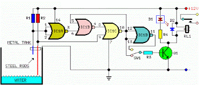
Automatic water pump controller is a series of functions to control the Automatic Water Pump Controller Circuit in a reservoir or water storage. As the water level sensor made with a metal plate mounted on the reservoir or water tank, with a sensor in the short to create the top level and a detection sensor for detecting long again made the lower level and ground lines connected to the bottom of reservoirs or reservoir. The series of automatic water pump controller is designed with 2 inputs NOR by 4 pieces and relay that is activated by the transistor. Automatic water pump circuit requires +12 VDC voltage source and can be used to control the water pump is connected to AC power . Here is the complete series of pictures.
Series Automatic Water Pump Controller
List Component Automatic Water Pump Controller
R1 = 15K
R2 = 15K
R3 = 10K
R4 = 1K
D1 = LED
D2 = 1N4148
Q1 = BC337
IC1 = 4001
SW = SPDT Switches
Relay RL1 = 12V
The working principle series of automatic water pump controller above is. At the time the water level is below both sensors, the output IC1C (pin 10) will be LOW, Kemudin when the water began to touch the lower level sensor, the output IC1C (pin10) remains LOW until the water touches the sensor level above, then the output IC1C (pin 10) going HIGH and active relay through Q1 and turn on the water pump to meguras reservoir. At the muli down and water level sensors for water untouched MKA IC1C output (pin 10) remains HIGH until the new water untouched semuasensor IC1C output (pin 10) LOW and water pump died. The series of automatic water pump controller is equipped with SW1 which serves to reverse the logic of drains (the output of IC1C) and the concept of water supplied (output dri IC1D). When SW1 is connected to IC1D the water pump will turn on when the water does not touch all the sensors and will die when all the sensors tesentuh water. Automatic water pump controller can be used to fill or drain the water according to which mode is selected via SW1.

Thursday, December 19, 2013
Numeric Water Level Indicator
Most water-level indicators for water tanks are based upon the number of LEDs that glow to indicate the corresponding level of water in the container. Here we present a digital version of the water-level indicator. It uses a 7-segment display to show the water level in numeric form from0 to 9. The circuit works off 5V regulated power supply. It is built around priority encoder IC 74HC147 (IC1), BCD-to-7-segment decoder IC CD4511 (IC2), 7-segment display LTS543 (DIS1) and a few discrete components. Due to high input impedance, IC1 senses water in the container from its nine input terminals. The inputs are connected to +5V via 560-kilo-ohm resistors.
Numeric Water-Level Indicator Circuit diagram

The ground terminal of the sensor must be kept at the bottom of the container (tank). IC 74HC147 has nine active-low inputs and converts the active input into active-low BCD output. The input L-9 has the highest priority. The outputs of IC1 (A, B, C and D) are fed to IC2 via transistors T1 through T4. This logic inverter is used to convert the active-low output of IC1 into active-high for IC2. The BCD code received by IC2 is shown on 7-segment display LTS543. Resistors R18 through R24 limit the current through the display.
When the tank is empty, all the inputs of IC1 remain high. As a result, its output also remains high, making all the inputs of IC2 low. Display LTS543 at this stage shows 0, which means the tank is empty. Similarly, when the water level reaches L-1 position, the display shows 1, and when the water level reaches L-8 position, the display shows 8. Finally, when the tank is full, all the inputs of IC1 become low and its output goes low to make all the inputs of IC2 high. Display LTS543 now shows 9, which means the tank is full. Assemble the circuit on a general-purpose PCB and enclose in a box. Mount 7-segment LTS543 on the front panel of the box. For sensors L-1 though L-9 and ground, use corrosion-free conductive-metal (stainless-steel) strips.
Numeric Water-Level Indicator Circuit diagram
When the tank is empty, all the inputs of IC1 remain high. As a result, its output also remains high, making all the inputs of IC2 low. Display LTS543 at this stage shows 0, which means the tank is empty. Similarly, when the water level reaches L-1 position, the display shows 1, and when the water level reaches L-8 position, the display shows 8. Finally, when the tank is full, all the inputs of IC1 become low and its output goes low to make all the inputs of IC2 high. Display LTS543 now shows 9, which means the tank is full. Assemble the circuit on a general-purpose PCB and enclose in a box. Mount 7-segment LTS543 on the front panel of the box. For sensors L-1 though L-9 and ground, use corrosion-free conductive-metal (stainless-steel) strips.
Monday, November 11, 2013
Transistor Water Sensor Alarm
This water sensor alarm circuit diagram is designed using common electronic components. Thewater sensor alarm circuit may operate an active buzzer, to make a sound when is reached a certain level of water.
Transistor Water Sensor Alarm Circuit Diagram

Because water sensor and control circuit for buzzer are located on the same printed circuit board, indicator, together with 9 V battery and buzzer can be mounted in a compact case.
When water reaches the sensor, the base of T1 is connected to the positive supply terminal. Therefore, T1 and T2 are open, so that buzzer BZ1, will be activated. Sensitivity reduction of the circuit can be done by increasing the value of R2.
Transistor Water Sensor Alarm Circuit Diagram
When water reaches the sensor, the base of T1 is connected to the positive supply terminal. Therefore, T1 and T2 are open, so that buzzer BZ1, will be activated. Sensitivity reduction of the circuit can be done by increasing the value of R2.
Subscribe to:
Posts (Atom)