Showing posts with label indicator. Show all posts
Showing posts with label indicator. Show all posts
Saturday, December 21, 2013
Very Simple Peak Indicator Circuit
This series is made to indicate that the amplifier has been given the maximum signal, the amplifier has the ability to be at its peak. if the lights do not mean the signal-plus volume. the way it works is the LED lights will light up when given a signal that more than 1.8 volts, the average amplifier will be saturated (maximum) if the signal was given more than this.

The circuit is very simple to the point that we forget that making a series of peak signal can in this way. circuit is mounted on the output tone control IC, master mixer output, or input power amplifier. This series does not impose on other circuits. survived the experiment!

Thursday, December 19, 2013
Numeric Water Level Indicator
Most water-level indicators for water tanks are based upon the number of LEDs that glow to indicate the corresponding level of water in the container. Here we present a digital version of the water-level indicator. It uses a 7-segment display to show the water level in numeric form from0 to 9. The circuit works off 5V regulated power supply. It is built around priority encoder IC 74HC147 (IC1), BCD-to-7-segment decoder IC CD4511 (IC2), 7-segment display LTS543 (DIS1) and a few discrete components. Due to high input impedance, IC1 senses water in the container from its nine input terminals. The inputs are connected to +5V via 560-kilo-ohm resistors.
Numeric Water-Level Indicator Circuit diagram

The ground terminal of the sensor must be kept at the bottom of the container (tank). IC 74HC147 has nine active-low inputs and converts the active input into active-low BCD output. The input L-9 has the highest priority. The outputs of IC1 (A, B, C and D) are fed to IC2 via transistors T1 through T4. This logic inverter is used to convert the active-low output of IC1 into active-high for IC2. The BCD code received by IC2 is shown on 7-segment display LTS543. Resistors R18 through R24 limit the current through the display.
When the tank is empty, all the inputs of IC1 remain high. As a result, its output also remains high, making all the inputs of IC2 low. Display LTS543 at this stage shows 0, which means the tank is empty. Similarly, when the water level reaches L-1 position, the display shows 1, and when the water level reaches L-8 position, the display shows 8. Finally, when the tank is full, all the inputs of IC1 become low and its output goes low to make all the inputs of IC2 high. Display LTS543 now shows 9, which means the tank is full. Assemble the circuit on a general-purpose PCB and enclose in a box. Mount 7-segment LTS543 on the front panel of the box. For sensors L-1 though L-9 and ground, use corrosion-free conductive-metal (stainless-steel) strips.
Numeric Water-Level Indicator Circuit diagram
When the tank is empty, all the inputs of IC1 remain high. As a result, its output also remains high, making all the inputs of IC2 low. Display LTS543 at this stage shows 0, which means the tank is empty. Similarly, when the water level reaches L-1 position, the display shows 1, and when the water level reaches L-8 position, the display shows 8. Finally, when the tank is full, all the inputs of IC1 become low and its output goes low to make all the inputs of IC2 high. Display LTS543 now shows 9, which means the tank is full. Assemble the circuit on a general-purpose PCB and enclose in a box. Mount 7-segment LTS543 on the front panel of the box. For sensors L-1 though L-9 and ground, use corrosion-free conductive-metal (stainless-steel) strips.
Thursday, November 21, 2013
Audio peak indicator circuit

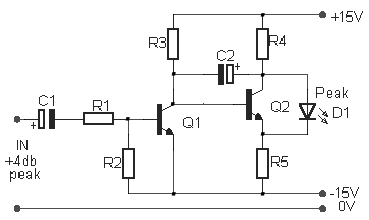
The existence of the peak indicator (Audio Peak Indicator) in an audio device is needed. Audio Peak indicator is a simple circuit to detect the peak level of audio signal. Audio Peak indicator circuit is built with duabuah transistor and LED indicator as peak level detection of audio signals.
The main function of a series of Audio Peak indicator is to determine the occurrence of the peak level of audio signal which is more than +4 dB, equivalent to 1.25 V rms. If the received audio signal Audio Peak Indicator more than +4 dB was the LEDs in series Peak Audio This indicator will light. Audio Peak indicator circuit is mounted on the output audio system.
 |
| Audio peak indicator |
R1 = 10Kohm
R2 = 1.2Kohm
R3 = 220Kohm
R4 = 4.7Kohm
R5 = 4.7Kohm
C1 = 47uF 25V
C2 = 2.2uF 25V
Q1 = BC550C
Q2 = BC550C
D1 = Red Led
Thursday, November 14, 2013
Arrow LED Indicator using 74hc14 IC
This arrow led indicator electronic project can be used in some dark places to show the directions . You can use to indicate direction just an illuminated arrow or a flashing light , but is much nicer if the light moves in the correct direction.
This arrow led indicator is based on 74HC14 circuit and some LEDs which are used to show the way .
For this arrow led indicator we need six series of three LEDs arranged in the shape of arrows and are connected to the outputs . Each time the lit arrows move over by one column so it appears that the arrows run from right to left.
Arrow LED Indicator Circuit Diagram

If we want to change the speed of the moving light it’s need to change the value of C1 to C3 or R1 to R3 ( a lower value for this components decrease the time of moving lights). If we want a longer arrow we can mount in parallel with existing columns another columns .
For power supply we can use batteries or 6V regulated power supply .
This arrow led indicator is based on 74HC14 circuit and some LEDs which are used to show the way .
For this arrow led indicator we need six series of three LEDs arranged in the shape of arrows and are connected to the outputs . Each time the lit arrows move over by one column so it appears that the arrows run from right to left.
Arrow LED Indicator Circuit Diagram
If we want to change the speed of the moving light it’s need to change the value of C1 to C3 or R1 to R3 ( a lower value for this components decrease the time of moving lights). If we want a longer arrow we can mount in parallel with existing columns another columns .
For power supply we can use batteries or 6V regulated power supply .
Thursday, October 17, 2013
Equipment Indicator Using Two LED
This simple circuit aims to provide an indication of an appliance if it is ON or OFF with the use of green and red LEDs.
The indication produced by the LEDs could mean that the red LED will illustrate that the equipment is turned ON while the green LED will illuminate upon turning OFF the same appliance. It could also be the other way around since green normally signifies that there is life on an equipment. This is applicable with any appliance that is powered and operated by AC mains which can be 230 V or 115 Vac.
A suitable switch SW1 made of single pole single throw type will be capable of handling the full load current. These switches can be in the form of toggle switch, push-to-make switch, push-push switch, tilt switch, reed switch, DIP switch, or push-to-break switch. During the operation, the load and the red diode D4 are being energized when the contacts of switch SW1 is closed. At this stage, the transistor Q1 will get saturated and shorts the green diode D3 which prevents it from illuminating.
Equipment Indicator Using Two LED Schematic
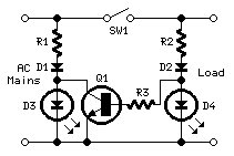
The explanation of the circuit operation pertains to a 230 Vac source. If the source would be coming from 115 Vac mains, the value of R1 and R2 should b3 15K Ohms at 1 W power output. The use of the type of switch SW1 should be able to withstand the full load voltage and current of the equipment.The two LED indicator can are widely used in several equipments and gadgets like the mobile phones. A blackberry phone have a LED indicator that can provide four colors depending on the status of the phone if it is receiving a message or a call, if connected via Wi-Fi, or if connected via Bluetooth. The good thing about the circuit is that it can be used for emergency light indicator, signal light, backup light, dashboard light, or with flash buzzer based on the AD signal light.
- BC337 – a small signal NPN Silicon AF medium power transistor used for general purpose switching and amplifying applications with features such as TO-18 manufactured package, suited for AF driver stages and low power output stages, and divided into three group types.
- Single Pole Single Throw (SPST) – a single on-off switch where the two terminals are either connected together of not connected to anything
The indication produced by the LEDs could mean that the red LED will illustrate that the equipment is turned ON while the green LED will illuminate upon turning OFF the same appliance. It could also be the other way around since green normally signifies that there is life on an equipment. This is applicable with any appliance that is powered and operated by AC mains which can be 230 V or 115 Vac.
A suitable switch SW1 made of single pole single throw type will be capable of handling the full load current. These switches can be in the form of toggle switch, push-to-make switch, push-push switch, tilt switch, reed switch, DIP switch, or push-to-break switch. During the operation, the load and the red diode D4 are being energized when the contacts of switch SW1 is closed. At this stage, the transistor Q1 will get saturated and shorts the green diode D3 which prevents it from illuminating.
Equipment Indicator Using Two LED Schematic
The explanation of the circuit operation pertains to a 230 Vac source. If the source would be coming from 115 Vac mains, the value of R1 and R2 should b3 15K Ohms at 1 W power output. The use of the type of switch SW1 should be able to withstand the full load voltage and current of the equipment.The two LED indicator can are widely used in several equipments and gadgets like the mobile phones. A blackberry phone have a LED indicator that can provide four colors depending on the status of the phone if it is receiving a message or a call, if connected via Wi-Fi, or if connected via Bluetooth. The good thing about the circuit is that it can be used for emergency light indicator, signal light, backup light, dashboard light, or with flash buzzer based on the AD signal light.
Wednesday, October 16, 2013
Temperature Indicator
This temperature indicator indicates the temperature of a heat sink in high power circuits .In this temperature indicator, diode voltage drop in ambient temperature is used as reference level. Temperature is measured by a transistor mounted on a radiator or near power transistor controlled.T1 temperature sensor and voltage to the base - emitter is compared, through potentiometer P1, with the common point of reference in its D1 and R1. Transistor remains blocked as long as temperature remains below a certain level, which is set to P1. Base-emitter voltage of transistor will decrease by about 2 mV for a temperature increase of about 1 ° C.
When the emitter voltage of transistor voltage falls below the cursor P1, the transistor will go into conduction and D2 will light.The values of R1 and R2 are voltage dependence of Ub and relationships can be calculated:
R1 = [(Ub - 0.6) / 5] k, R2 = [(Ub - 1.5) / 15] k.
Temperature Indicator Schematic
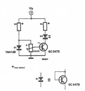
When the emitter voltage of transistor voltage falls below the cursor P1, the transistor will go into conduction and D2 will light.The values of R1 and R2 are voltage dependence of Ub and relationships can be calculated:
R1 = [(Ub - 0.6) / 5] k, R2 = [(Ub - 1.5) / 15] k.
Temperature Indicator Schematic
Wednesday, October 9, 2013
12V battery indicator level
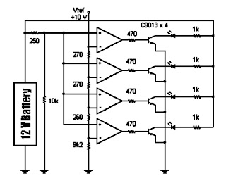
 The following sequence is useful to show the battery voltage (battery) 12 volts. Voltage level is shown with four lights led. To facilitate the reading of the led is arranged in a vertical array. Led top three chosen by the green LED while the lowest is selected the color red. If the battery voltage continues to decline (because of usage), the Led-Led will turn off sequentially from the top to the bottom.
Until if battery voltage is below 11.83 volts then only the red LED that lights up which means that the charge batteries are empty. Even this red Led will die if the stress continues to drop to below 11.5 volts. The working principle of this circuit is a comparison of battery voltage with a reference voltage.
Schematic Battery level indicator
Wednesday, October 2, 2013
Blown Fuse Indicator
Here is a simple scheme for adding a blown fuse indicator to your existing power supply circuit. This is done by just adding a resistor and LED to the existing circuit. The LED and resistor are connected in series and this combination is connected in parallel to the existing fuse. When the fuse is intact, it offers a low resistance and so the voltage drop across it will be not sufficient enough to glow the LED. When the fuse is blown off, it is equivalent to infinite resistance and so the entire power supply will drop across the resistor LED series combination and makes the LED glow. The resistance R1 is used to limit the current through LED.
Blown Fuse Indicator Circuit Diagram
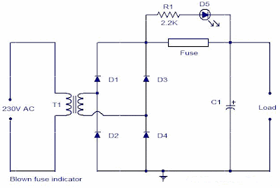
The component values of other components are not given in the diagram because it depends on your specific power supply requirements. Any way for a conventional 12V power supply the component values are as follows: 1N4007 for D1,D2,D3 and D4; 230V primary,12V secondary ,2A step-down transformer for T1, 2A fuse and a 1000uF/25V capacitor for C1.
Notes.
Blown Fuse Indicator Circuit Diagram
The component values of other components are not given in the diagram because it depends on your specific power supply requirements. Any way for a conventional 12V power supply the component values are as follows: 1N4007 for D1,D2,D3 and D4; 230V primary,12V secondary ,2A step-down transformer for T1, 2A fuse and a 1000uF/25V capacitor for C1.
Notes.
- Assemble the circuit on a general purpose PCB.
- The circuit will not work if the load is not connected.
- A highly resistive load may also impart the working of the circuit.
- The components for this circuit can easily obtained from your electronic junk box.
Sunday, September 29, 2013
Phone Busy Indicator Diagram
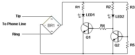 Phone Busy Indicator Diagram
Have you anytime been application the modem or fax and addition abroad picks up the phone, breaking the connection? Well, this simple ambit should put an end to that. It signals that the buzz is in use by lighting a red LED. When the buzz is not in use, a blooming LED is lit. It needs no alien ability and can be affiliated anywhere on the buzz line, alike army central the phone.
Notes
1. This is a very simple circuit and is easily made on a perf board and mounted inside the phone.
2. LED1 and LED2 flash on and off while the phone is ringing.
3. Do not worry about mixing up the Tip and Ring connections.
4. The ring voltage on a phone line is anywhere from 90 to 130 volts. Make sure no one calls while you are making the line connections or youll know it. :-)
5. In some countries or states you will have to ask the phone company before you connect this to the line. It might even require an inspection.
6. If the circuit causes distortion on the phone line, connect a 680 ohm resistor in between one of the incoming line wires and the bridge rectifier.
Phone Busy Indicator Diagram Part List
R1 1 3.3K 1/4 W Resistor
R2 1 33K 1/4 W Resistor
R3 1 56K 1/4 W Resistor
R4 1 22K 1/4 W Resistor
R5 1 4.7K 1/4 W Resistor
Q1, Q2 2 2N3392 NPN Transistor
BR1 1 1.5 Amp 250 PIV Bridge Rectifier
LED1 1 Red LED
LED2 1 Green LED
MISC 1 Wire, Case, Phone Cord
Monday, September 23, 2013
Audio Peak Indicator Circuit
The existence of the peak indicator "Audio Peak Indicator" in an audio device is needed. Audio Peak indicator is a simple circuit to detect the peak level of audio signal. Audio Peak indicator circuit is built with duabuah transistor and LED indicator as peak level detection of audio signals.
The main function of a series of Audio Peak indicator is to determine the occurrence of the peak level of audio signal that is more than +4 dB, equivalent to 1.25 V rms. If the received audio signal Audio Peak Indicator more than +4 dB was the LEDs in series Peak Audio This indicator will light. Audio Peak indicator circuit is mounted on the output audio system.
The main function of a series of Audio Peak indicator is to determine the occurrence of the peak level of audio signal that is more than +4 dB, equivalent to 1.25 V rms. If the received audio signal Audio Peak Indicator more than +4 dB was the LEDs in series Peak Audio This indicator will light. Audio Peak indicator circuit is mounted on the output audio system.

R1 = 10Kohm
R2 = 1.2Kohm
R3 = 220Kohm
R4-5 = 4.7Kohm
C1 = 47uF 25V
C2 = 2.2uF 25V
Q1-2 = BC550C
D1 = LED RED
We hope to form the reference materials in the manufacture of circuit pernagkat Audio Peak Indicators in the audio readers.
Subscribe to:
Posts (Atom)