Showing posts with label temperature. Show all posts
Showing posts with label temperature. Show all posts
Saturday, October 18, 2014
Simple Temperature Sensor Arduino
Hello people, it’s been a while since I have posted projects on this website. This semester was really busy, I didn’t have time to much else, but soon I will have my winter holiday (Here in south our summer holiday is from December to February).
Today I am going to show you how to build a simple temperature sensor using one LM35 Precision Temperature Sensor and Arduino, so you can hookup on your future projects. The circuit will send serial information about the temperature so you can use on your computer, change the code as you will. I’m planning to build a temperature sensor with max/min + clock + LCD, and when I get it done, I will post here.
Parts:
This is a quick and simple step. Just connect the 5V output from arduino to the 1st pin of the sensor, ground the 3rd pin and the 2nd one, you connect to the 0 Analog Input.
Down goes some pictures that may help you, click to enlarge:


Here is the Arduino Code, just upload it and check the Serial Communication Option.
You can also download the .pde HERE.
Anything just ask!
Source by : link
Today I am going to show you how to build a simple temperature sensor using one LM35 Precision Temperature Sensor and Arduino, so you can hookup on your future projects. The circuit will send serial information about the temperature so you can use on your computer, change the code as you will. I’m planning to build a temperature sensor with max/min + clock + LCD, and when I get it done, I will post here.
Parts:
- Arduino (You can use other microcontroller, but then you will need to change the code).
- LM35 Precision Centigrade Temperature Sensor, you can get from any electronic store. Here is the DATA SHEET.
- BreadBoard
This is a quick and simple step. Just connect the 5V output from arduino to the 1st pin of the sensor, ground the 3rd pin and the 2nd one, you connect to the 0 Analog Input.
Down goes some pictures that may help you, click to enlarge:
Here is the Arduino Code, just upload it and check the Serial Communication Option.
You can also download the .pde HERE.
/*
An open-source LM35DZ Temperature Sensor for Arduino. This project will be enhanced on a regular basis
(cc) by Daniel Spillere Andrade , http://www.danielandrade.net
http://creativecommons.org/license/cc-gpl
*/
int pin = 0; // analog pin
int tempc = 0,tempf=0; // temperature variables
int samples[8]; // variables to make a better precision
int maxi = -100,mini = 100; // to start max/min temperature
int i;
void setup()
{
Serial.begin(9600); // start serial communication
}
void loop()
{
for(i = 0;i< =7;i++){ // gets 8 samples of temperature
samples[i] = ( 5.0 * analogRead(pin) * 100.0) / 1024.0;
tempc = tempc + samples[i];
delay(1000);
}
tempc = tempc/8.0; // better precision
tempf = (tempc * 9)/ 5 + 32; // converts to fahrenheit
if(tempc > maxi) {maxi = tempc;} // set max temperature
if(tempc < mini) {mini = tempc;} // set min temperature
Serial.print(tempc,DEC);
Serial.print(" Celsius, ");
Serial.print(tempf,DEC);
Serial.print(" fahrenheit -> ");
Serial.print(maxi,DEC);
Serial.print(" Max, ");
Serial.print(mini,DEC);
Serial.println(" Min");
tempc = 0;
delay(1000); // delay before loop
}
An open-source LM35DZ Temperature Sensor for Arduino. This project will be enhanced on a regular basis
(cc) by Daniel Spillere Andrade , http://www.danielandrade.net
http://creativecommons.org/license/cc-gpl
*/
int pin = 0; // analog pin
int tempc = 0,tempf=0; // temperature variables
int samples[8]; // variables to make a better precision
int maxi = -100,mini = 100; // to start max/min temperature
int i;
void setup()
{
Serial.begin(9600); // start serial communication
}
void loop()
{
for(i = 0;i< =7;i++){ // gets 8 samples of temperature
samples[i] = ( 5.0 * analogRead(pin) * 100.0) / 1024.0;
tempc = tempc + samples[i];
delay(1000);
}
tempc = tempc/8.0; // better precision
tempf = (tempc * 9)/ 5 + 32; // converts to fahrenheit
if(tempc > maxi) {maxi = tempc;} // set max temperature
if(tempc < mini) {mini = tempc;} // set min temperature
Serial.print(tempc,DEC);
Serial.print(" Celsius, ");
Serial.print(tempf,DEC);
Serial.print(" fahrenheit -> ");
Serial.print(maxi,DEC);
Serial.print(" Max, ");
Serial.print(mini,DEC);
Serial.println(" Min");
tempc = 0;
delay(1000); // delay before loop
}
Anything just ask!
Source by : link

Wednesday, December 18, 2013
12V 4 AA Cell Differential Temperature Charger
This project includes a number of improvements over my older Temperature Controlled NICD Charger circuit. This circuit runs on 12VDC, allowing it to be used in a car or from a 12V solar power system. Additionally, a current sensor LED verifies that the cells are receiving charging current. Note that the current sensor circuitry is not shown in the circuit board photo above, it was added to the side of the main board via a small perfboard.
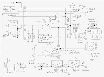
12V, 4-AA Cell Differential Temperature Charger Circuit diagram
The current is adjustable in three steps from 100 to 300mA, allowing fast charging of AA, AAA or other small cells. Battery packs from 1 to 6 cells can be charged with this circuit. NiMH and older NiCD cells are supported. The circuit is protected from reverse input voltage and reversed cells.
Connections:
12VDC power is supplied to the circuit from an external source such as a car battery system, a 12V solar power system or a regulated "wall wart" supply. If DC power is applied backwards, the 6A05 crowbar diode causes the 3A fuse to blow, protecting the circuit from reverse voltage. The power switch routes power to the 78L09 voltage regulator and the battery. The 78L09 regulator provides regulated power to the rest of the circuit.
The battery current loop starts with the +12V supply, then runs through the battery and through a 1N5819 reverse voltage protection diode. Current continues through the LM317 1 amp adjustable voltage regulator which is wired as a constant current source, through the IRFD110 power MOSFET transistor, which switches charging current on and off, through the 0.1 ohm current sensing resistor to ground (12VDC negative). The charge current is selected by jumpering one of three current-set resistors on the negative side of the LM317 regulator. The 120 ohm trickle charge resistor always allows 10mA of current to flow through the battery.
The temperature control part of the circuit starts with a matched pair of 10K NTC thermistors. One thermistor is epoxied to a small metal reference temperature plate. The other thermistor is epoxied to a metal battery holder. The temperature sensors are balanced by the calibrate potentiometer. The 100nF and 50nF capacitors across the thermistors cause different start-up time delays to insure that the following circuitry powers up in the off state.
The upper half of the TLC2272CP rail-to-rail op-amp is wired as a latching comparator when the Cal/Latch jumper is present (operate mode), the circuit becomes a regular comparator with hysteresis when the jumper is off (calibrate mode). Assuming the battery is cold and the circuit is in operate mode, the start switch turns the op-amp on for a charging cycle. When the battery temperature exceeds the reference temperature, the op-amp turns off and the diode in the feedback loop latches the op-amp off. The op-amp output also drives the IRFD110 current switch MOSFET.
The lower half of the TLC2272CP simply inverts the output from the upper part of the op-amp, this gives a bipolar drive signal for running the Red/Green Charging/Done light.
An optional current flow lamp was added to the circuit. Rechargeable batteries tend to get corroded contacts which can prevent the charging current from flowing. The lamp provides an indication that the charging current is really making its way through the batteries. The current Flow lamp circuit consists of an LM358 op-amp wired as a current measurement amplifier that monitors the voltage drop across a 0.1 ohm resistor. The LM358 is specially suited for this type of circuit. The output of the first LM358 stage is further boosted and offset by the second LM358 stage. This produces a digital signal that drives the indicator LED through a current limiting resistor. If you dont want to add the Current Flow circuit, replace the 0.1 ohm resistor with a wire jumper.
Construction:
The circuit was built on a custom home-built circuit board, a hand-wired perf board would also make a good platform for this project. The LM317 regulator is mounted on an aluminum heat sink under the main board, the heat sink should be kept away from the two temperature sensors. The reference temperature sensor is mounted to a small piece of aluminum that is thermally isolated from the battery holder and the rest of the circuitry. All of the sub-components are mounted on a piece of plexiglass or another non conducting material.
Calibration:
Put the circuit in one location and allow the temperature to stabilize for an hour or so. Remove the Cal/[Latch] jumper. Adjust the 20 turn Calibrate trimmer a little bit past the point where the Charge/Done light turns red. Put the Cal/[Latch] jumper back.
Use:
The charger should only be used in a cool location with a fairly constant temperature. Install the batteries to charge in the battery holder, start with the negative side of the socket and connect the alligator clip to the + side of the last cell. Put a piece of insulating foam over the battery holder to keep the warmth in the battery. If the battery is already hot, allow it to cool down before starting the charge cycle. The Charging/Done light should now be green.
Push the Start switch and the Charging/Done light should turn red. The Current Flow light should turn on, if it doesnt, try reseating the cells in the holder. After some amount of charging, the battery will warm up, the Charging/Done light will turn green and the battery charge cycle be finished. If you want to equalize the weaker cells in the battery, allow the pack to cool down then run another charging cycle, the second time should not take very long.
12V, 4-AA Cell Differential Temperature Charger Circuit diagram
The current is adjustable in three steps from 100 to 300mA, allowing fast charging of AA, AAA or other small cells. Battery packs from 1 to 6 cells can be charged with this circuit. NiMH and older NiCD cells are supported. The circuit is protected from reverse input voltage and reversed cells.
Connections:
- 12VDC (nominal) power input
- Connections for the Battery Under Charge
- Power On/Off switch
- Charge Start switch
- 3 step Charge Current Select jumper
- Calibrate/[Latch] mode jumper
- Temperature sensor calibrate trimmer
- Red/Green Charging/Done light
- Amber Current Flow light
12VDC power is supplied to the circuit from an external source such as a car battery system, a 12V solar power system or a regulated "wall wart" supply. If DC power is applied backwards, the 6A05 crowbar diode causes the 3A fuse to blow, protecting the circuit from reverse voltage. The power switch routes power to the 78L09 voltage regulator and the battery. The 78L09 regulator provides regulated power to the rest of the circuit.
The battery current loop starts with the +12V supply, then runs through the battery and through a 1N5819 reverse voltage protection diode. Current continues through the LM317 1 amp adjustable voltage regulator which is wired as a constant current source, through the IRFD110 power MOSFET transistor, which switches charging current on and off, through the 0.1 ohm current sensing resistor to ground (12VDC negative). The charge current is selected by jumpering one of three current-set resistors on the negative side of the LM317 regulator. The 120 ohm trickle charge resistor always allows 10mA of current to flow through the battery.
The temperature control part of the circuit starts with a matched pair of 10K NTC thermistors. One thermistor is epoxied to a small metal reference temperature plate. The other thermistor is epoxied to a metal battery holder. The temperature sensors are balanced by the calibrate potentiometer. The 100nF and 50nF capacitors across the thermistors cause different start-up time delays to insure that the following circuitry powers up in the off state.
The upper half of the TLC2272CP rail-to-rail op-amp is wired as a latching comparator when the Cal/Latch jumper is present (operate mode), the circuit becomes a regular comparator with hysteresis when the jumper is off (calibrate mode). Assuming the battery is cold and the circuit is in operate mode, the start switch turns the op-amp on for a charging cycle. When the battery temperature exceeds the reference temperature, the op-amp turns off and the diode in the feedback loop latches the op-amp off. The op-amp output also drives the IRFD110 current switch MOSFET.
The lower half of the TLC2272CP simply inverts the output from the upper part of the op-amp, this gives a bipolar drive signal for running the Red/Green Charging/Done light.
An optional current flow lamp was added to the circuit. Rechargeable batteries tend to get corroded contacts which can prevent the charging current from flowing. The lamp provides an indication that the charging current is really making its way through the batteries. The current Flow lamp circuit consists of an LM358 op-amp wired as a current measurement amplifier that monitors the voltage drop across a 0.1 ohm resistor. The LM358 is specially suited for this type of circuit. The output of the first LM358 stage is further boosted and offset by the second LM358 stage. This produces a digital signal that drives the indicator LED through a current limiting resistor. If you dont want to add the Current Flow circuit, replace the 0.1 ohm resistor with a wire jumper.
Construction:
The circuit was built on a custom home-built circuit board, a hand-wired perf board would also make a good platform for this project. The LM317 regulator is mounted on an aluminum heat sink under the main board, the heat sink should be kept away from the two temperature sensors. The reference temperature sensor is mounted to a small piece of aluminum that is thermally isolated from the battery holder and the rest of the circuitry. All of the sub-components are mounted on a piece of plexiglass or another non conducting material.
Calibration:
Put the circuit in one location and allow the temperature to stabilize for an hour or so. Remove the Cal/[Latch] jumper. Adjust the 20 turn Calibrate trimmer a little bit past the point where the Charge/Done light turns red. Put the Cal/[Latch] jumper back.
Use:
The charger should only be used in a cool location with a fairly constant temperature. Install the batteries to charge in the battery holder, start with the negative side of the socket and connect the alligator clip to the + side of the last cell. Put a piece of insulating foam over the battery holder to keep the warmth in the battery. If the battery is already hot, allow it to cool down before starting the charge cycle. The Charging/Done light should now be green.
Push the Start switch and the Charging/Done light should turn red. The Current Flow light should turn on, if it doesnt, try reseating the cells in the holder. After some amount of charging, the battery will warm up, the Charging/Done light will turn green and the battery charge cycle be finished. If you want to equalize the weaker cells in the battery, allow the pack to cool down then run another charging cycle, the second time should not take very long.
Saturday, November 16, 2013
Fan control temperature using sensor LM35

Basic circuit of the LM35 are made to control the fan is either used on amplifier that requires automatic cooling. Its use on power amplifier circuit above and only requires DC fan. From basic sensors based on ic and amplifier op-amp is added again to the transistor Q1 to drive the fan.
Part List :
R1___220K
R2___100K
R3___3K3
R4___22K
R5___1M
R6___150R
R7___2K2
R8___33R 4W
C1___100pF
D1___1N4148
IC1__7915
IC2__TL072
IC3__LM35
F1___DC Fan 12V
Saturday, November 9, 2013
Temperature Pressure Load Force Other Sensors
LMP90xxx personal - Multi-Channel 16- & 24-small piece Sensor AFEs
The LMP90xxx Sensor AFE family skin the industrys merely low-power, fully configurable 16- and 24-spot ΣΔ ADCs with veritable constant background calibration, eliminating get and offset drift larger than while and high temperature and making them ideal in support of essential performance and low power applications.
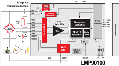 |
| LMP90100 Bridge and Temperature Sensors |
- Multi-channel Sensor AFE with a 16- before 24-smidgen Sigma Delta ADC underlying
- Flexible, programmable mux (4 differential, 7 single-ended, or else a combination inputs)
- permanent background sensor diagnostics reduces downtime and improves procedure efficiency
- Quick design and evaluation
- Ideal used for sharp-precision, multi-sensor hotness, pressure, load, and force applications
- industrialized, process control, health check, and test & measurement applications
LMP90xxx Sensor AFE Portfolio
| Resolution | Current Sources | Inputs | |
| 4 Diff / 7 SE | 2 Diff / 4 SE | ||
| 24-bit | Yes | LMP90100 | LMP90098 |
| 24-bit | No | LMP90099 | LMP90097 |
| 16-bit | Yes | LMP90080 | LMP90078 |
| 16-bit | No | LMP90079 | LMP90077 |
Wednesday, October 16, 2013
Temperature Indicator
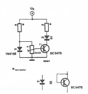
This temperature indicator indicates the temperature of a heat sink in high power circuits .In this temperature indicator, diode voltage drop in ambient temperature is used as reference level. Temperature is measured by a transistor mounted on a radiator or near power transistor controlled.T1 temperature sensor and voltage to the base - emitter is compared, through potentiometer P1, with the common point of reference in its D1 and R1. Transistor remains blocked as long as temperature remains below a certain level, which is set to P1. Base-emitter voltage of transistor will decrease by about 2 mV for a temperature increase of about 1 ° C.
When the emitter voltage of transistor voltage falls below the cursor P1, the transistor will go into conduction and D2 will light.The values of R1 and R2 are voltage dependence of Ub and relationships can be calculated:
R1 = [(Ub - 0.6) / 5] k, R2 = [(Ub - 1.5) / 15] k.
Temperature Indicator Schematic
When the emitter voltage of transistor voltage falls below the cursor P1, the transistor will go into conduction and D2 will light.The values of R1 and R2 are voltage dependence of Ub and relationships can be calculated:
R1 = [(Ub - 0.6) / 5] k, R2 = [(Ub - 1.5) / 15] k.
Temperature Indicator Schematic
Subscribe to:
Posts (Atom)