Showing posts with label level. Show all posts
Showing posts with label level. Show all posts
Thursday, December 19, 2013
Numeric Water Level Indicator
Most water-level indicators for water tanks are based upon the number of LEDs that glow to indicate the corresponding level of water in the container. Here we present a digital version of the water-level indicator. It uses a 7-segment display to show the water level in numeric form from0 to 9. The circuit works off 5V regulated power supply. It is built around priority encoder IC 74HC147 (IC1), BCD-to-7-segment decoder IC CD4511 (IC2), 7-segment display LTS543 (DIS1) and a few discrete components. Due to high input impedance, IC1 senses water in the container from its nine input terminals. The inputs are connected to +5V via 560-kilo-ohm resistors.
Numeric Water-Level Indicator Circuit diagram

The ground terminal of the sensor must be kept at the bottom of the container (tank). IC 74HC147 has nine active-low inputs and converts the active input into active-low BCD output. The input L-9 has the highest priority. The outputs of IC1 (A, B, C and D) are fed to IC2 via transistors T1 through T4. This logic inverter is used to convert the active-low output of IC1 into active-high for IC2. The BCD code received by IC2 is shown on 7-segment display LTS543. Resistors R18 through R24 limit the current through the display.
When the tank is empty, all the inputs of IC1 remain high. As a result, its output also remains high, making all the inputs of IC2 low. Display LTS543 at this stage shows 0, which means the tank is empty. Similarly, when the water level reaches L-1 position, the display shows 1, and when the water level reaches L-8 position, the display shows 8. Finally, when the tank is full, all the inputs of IC1 become low and its output goes low to make all the inputs of IC2 high. Display LTS543 now shows 9, which means the tank is full. Assemble the circuit on a general-purpose PCB and enclose in a box. Mount 7-segment LTS543 on the front panel of the box. For sensors L-1 though L-9 and ground, use corrosion-free conductive-metal (stainless-steel) strips.
Numeric Water-Level Indicator Circuit diagram
When the tank is empty, all the inputs of IC1 remain high. As a result, its output also remains high, making all the inputs of IC2 low. Display LTS543 at this stage shows 0, which means the tank is empty. Similarly, when the water level reaches L-1 position, the display shows 1, and when the water level reaches L-8 position, the display shows 8. Finally, when the tank is full, all the inputs of IC1 become low and its output goes low to make all the inputs of IC2 high. Display LTS543 now shows 9, which means the tank is full. Assemble the circuit on a general-purpose PCB and enclose in a box. Mount 7-segment LTS543 on the front panel of the box. For sensors L-1 though L-9 and ground, use corrosion-free conductive-metal (stainless-steel) strips.

Music LED light level
This is a simple circuit. Music can change the LED light level gamut.
Operation of this circuit is a circuit op amp IC1 / 1-IC1 / 5 compared to the characteristics of the circuit voltage.It has one pin acts as a voltage reference pin.That the pressure from the supply voltage and divide between R1 and R7 pressure used in this circuit will be compared with the pressure drop across R7.
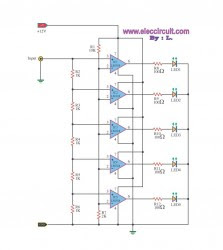 |
| Music LED light level |
As the 2V input side, it will be R2, R3, R4, R5, R6 series, keeping the pressure drop across.Each R as well.
If there is pressure to 5Vp-p is the voltage across R2 = R3 = R4 = R5 = R6 = 1V.The voltage reference, we have 2V. IC4 circuit compares the measured voltage at the input pin of IC4 is 2V.Which is equal pressure on the leg or legs plus the output of IC4 will not flow to drive the LED light will be more pressure input into this.IC4 to make work. The next LED arranged in the order of the input voltage.
source : http://www.eleccircuit.com/simple-led-light-based-music-using-lm318/
source : http://www.eleccircuit.com/simple-led-light-based-music-using-lm318/
Simple Fluid Level Sensor
A very simple fluid lever sensor can be designed using this circuit diagram . This fluid level sensor electronic circuit project is very simple and can be used to control water pump or to activate /stop some devices when the sensor detects presence of water.
Simple Fluid Level Sensor Circuit diagram

This fluid level sensor circuit uses an ac sensing signal to eliminate electrolytic corrosion on the probes .The ac signal rectified is used to drive T1 transistor that drives a 12 volt relay , that can activate or stop some device . R2 resistor is used to modify the sensor sensitivity and can be replaced with a small variable resistor . MC104093B is a p channel quad 2 input NAND schmitt trigger and is pin to pin compatible with the CD4093 . The unused inputs must be tied to an appropriate voltage level , either ground or +12 volts (8,9,12 and 13) and the unused outputs must be left open (10 and 11) .
The circuit can be powered with an input voltage between 3 and 18 volts dc , but in our case the circuit use a 12 volts DC power source .
Simple Fluid Level Sensor Circuit diagram
The circuit can be powered with an input voltage between 3 and 18 volts dc , but in our case the circuit use a 12 volts DC power source .
Wednesday, October 9, 2013
12V battery indicator level
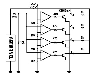
 The following sequence is useful to show the battery voltage (battery) 12 volts. Voltage level is shown with four lights led. To facilitate the reading of the led is arranged in a vertical array. Led top three chosen by the green LED while the lowest is selected the color red. If the battery voltage continues to decline (because of usage), the Led-Led will turn off sequentially from the top to the bottom.
Until if battery voltage is below 11.83 volts then only the red LED that lights up which means that the charge batteries are empty. Even this red Led will die if the stress continues to drop to below 11.5 volts. The working principle of this circuit is a comparison of battery voltage with a reference voltage.
Schematic Battery level indicator
Subscribe to:
Posts (Atom)