Showing posts with label two. Show all posts
Showing posts with label two. Show all posts
Saturday, October 18, 2014
Cross Linking With Two Patch Cables
In networks, the supremacy of coax cable is a thing of the past. Nowadays, Ethernet connections are made using UTP cables. The BNC plug has yielded to the 8-way RJ45 plug. Previously, coax cables were daisy-chained from computer to computer and terminated at the two ends using 50-_ resistors, but modern networks use central ‘socket boxes’ (switches and/or hubs) to interconnect everything. The connections between the hubs and the computers are made using patch cables having the same sequence of leads in the RJ45 connectors at each end. For making a direct connection between two computers without using a hub or switch, a ‘crossover cable’ is used.


 Such a cable has the leads cross-linked in order to allow the two computers to directly communicate with each other. If there are problems with the network, it can be handy to be able to directly interconnect twocomputers, or directly connect a computer to a cable or ADSL modem without using a hub or switch. A long crossover cable is not always available, and shoving around computers is not an attractive alternative. Consequently, we can use a dual RJ45 wall outlet box to construct an adapter, which can be used to interconnect the two patch cables coming from the equipment in question. This outlet box must be wired to create a cross-linked connection. This is done by making the following internal connections:


 Such a cable has the leads cross-linked in order to allow the two computers to directly communicate with each other. If there are problems with the network, it can be handy to be able to directly interconnect twocomputers, or directly connect a computer to a cable or ADSL modem without using a hub or switch. A long crossover cable is not always available, and shoving around computers is not an attractive alternative. Consequently, we can use a dual RJ45 wall outlet box to construct an adapter, which can be used to interconnect the two patch cables coming from the equipment in question. This outlet box must be wired to create a cross-linked connection. This is done by making the following internal connections:
- 1 → 3
- 2 → 6
- 3 → 1
- 4 → 4
- 5 → 5
- 6 → 2
- 7 → 7
- 8 → 8

Sunday, January 26, 2014
Simple Inverter with Two Transistors
The series below is a simple inverter circuit that will change the voltage of 12v dc to 220v ac, with use drive transistor 32 as its tip.
Inverter circuit is very simple and easy to assemble and is perfect for just starting to learn to assemble electronic circuits, you can use the transformer 2A to produce about 20 watts output. Do not forget to install coolers in its transistors. good luck.
Inverter circuit is very simple and easy to assemble and is perfect for just starting to learn to assemble electronic circuits, you can use the transformer 2A to produce about 20 watts output. Do not forget to install coolers in its transistors. good luck.

Thursday, October 17, 2013
Equipment Indicator Using Two LED
This simple circuit aims to provide an indication of an appliance if it is ON or OFF with the use of green and red LEDs.
The indication produced by the LEDs could mean that the red LED will illustrate that the equipment is turned ON while the green LED will illuminate upon turning OFF the same appliance. It could also be the other way around since green normally signifies that there is life on an equipment. This is applicable with any appliance that is powered and operated by AC mains which can be 230 V or 115 Vac.
A suitable switch SW1 made of single pole single throw type will be capable of handling the full load current. These switches can be in the form of toggle switch, push-to-make switch, push-push switch, tilt switch, reed switch, DIP switch, or push-to-break switch. During the operation, the load and the red diode D4 are being energized when the contacts of switch SW1 is closed. At this stage, the transistor Q1 will get saturated and shorts the green diode D3 which prevents it from illuminating.
Equipment Indicator Using Two LED Schematic
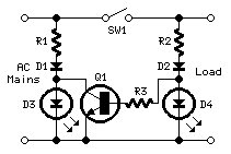
The explanation of the circuit operation pertains to a 230 Vac source. If the source would be coming from 115 Vac mains, the value of R1 and R2 should b3 15K Ohms at 1 W power output. The use of the type of switch SW1 should be able to withstand the full load voltage and current of the equipment.The two LED indicator can are widely used in several equipments and gadgets like the mobile phones. A blackberry phone have a LED indicator that can provide four colors depending on the status of the phone if it is receiving a message or a call, if connected via Wi-Fi, or if connected via Bluetooth. The good thing about the circuit is that it can be used for emergency light indicator, signal light, backup light, dashboard light, or with flash buzzer based on the AD signal light.
- BC337 – a small signal NPN Silicon AF medium power transistor used for general purpose switching and amplifying applications with features such as TO-18 manufactured package, suited for AF driver stages and low power output stages, and divided into three group types.
- Single Pole Single Throw (SPST) – a single on-off switch where the two terminals are either connected together of not connected to anything
The indication produced by the LEDs could mean that the red LED will illustrate that the equipment is turned ON while the green LED will illuminate upon turning OFF the same appliance. It could also be the other way around since green normally signifies that there is life on an equipment. This is applicable with any appliance that is powered and operated by AC mains which can be 230 V or 115 Vac.
A suitable switch SW1 made of single pole single throw type will be capable of handling the full load current. These switches can be in the form of toggle switch, push-to-make switch, push-push switch, tilt switch, reed switch, DIP switch, or push-to-break switch. During the operation, the load and the red diode D4 are being energized when the contacts of switch SW1 is closed. At this stage, the transistor Q1 will get saturated and shorts the green diode D3 which prevents it from illuminating.
Equipment Indicator Using Two LED Schematic
The explanation of the circuit operation pertains to a 230 Vac source. If the source would be coming from 115 Vac mains, the value of R1 and R2 should b3 15K Ohms at 1 W power output. The use of the type of switch SW1 should be able to withstand the full load voltage and current of the equipment.The two LED indicator can are widely used in several equipments and gadgets like the mobile phones. A blackberry phone have a LED indicator that can provide four colors depending on the status of the phone if it is receiving a message or a call, if connected via Wi-Fi, or if connected via Bluetooth. The good thing about the circuit is that it can be used for emergency light indicator, signal light, backup light, dashboard light, or with flash buzzer based on the AD signal light.
Subscribe to:
Posts (Atom)