Showing posts with label inverter. Show all posts
Showing posts with label inverter. Show all posts
Sunday, January 26, 2014
Simple Inverter with Two Transistors
The series below is a simple inverter circuit that will change the voltage of 12v dc to 220v ac, with use drive transistor 32 as its tip.
Inverter circuit is very simple and easy to assemble and is perfect for just starting to learn to assemble electronic circuits, you can use the transformer 2A to produce about 20 watts output. Do not forget to install coolers in its transistors. good luck.
Inverter circuit is very simple and easy to assemble and is perfect for just starting to learn to assemble electronic circuits, you can use the transformer 2A to produce about 20 watts output. Do not forget to install coolers in its transistors. good luck.


Sunday, January 12, 2014
Inverter 12V to 115V with 25 W power output
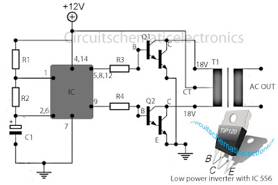
Low power inverter schematic are only use 9 components , one of which IC 556 , TIP120 NPN Darlington transistor.And turns 10 to 16 Vdc into 60 HZ, output 115 V square-wave power to operate ac equipment up to 25 W. In the circuit first ic originally hires as a timer chip m for stabilizatiom oscilator with components R1 and C1 setting frequency oscilator. Then the two transistor driver, drive the transformer push-pull fashion, When one transistor is biased on , the other circuit cut-off . The transformer is a 120V/18Vct unit that is connected backwards, so that it steps the voltage up rather than down. Oscilator circuit operates from about 4 to 16 V for stable output.
Part List :
R1 = 1K
R2 = 12K
R3 = 1K
R4 = 1/4W
C1 = 1uF
IC = 556
Q1 = TIP120
Q2 = TIP120
T1 = 120V 18VCT
Friday, December 27, 2013
Inverter 5000W with PWM Pulse Width Modulator
Inverter 5000W with PWM
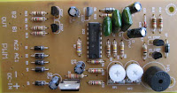
This inverter uses PWM (Pulse Width Modulator) with type IC SG3524. IC serves as a oscillator 50Hz, as a regulator of the desired output voltage. Input power ranging from 250W up to 5000W output and has. Following a series INVERTER 5000W with PWM (Pulse Width Modulator).
 |
| Schematic Inverter 5000W with PWM (Pulse Width Modulator) |
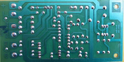 |
| Layout PCB Inverter 5000W with PWM (Pulse Width Modulator) |
below is the output power settings that can be issued by this inverter:
DC voltage and Transformer "T2" winding recommendation:
Winding Power Supply
12VDC 750W P: 24V "12-0-12" / S: 220V
1500W 24VDC P: 48V "24-0-24" / S: 220V
2250w 36VDC P: 72V "36-0-36" / S: 220V
3000w 48VDC P: 96V "48-0-48" / S: 220V
3750w 60VDC P: 120V "60-0-60" / S: 220V
4500w 72VDC P: 144V "72-0-72" / S: 220V
5250w 84VDC P: 168V "84-0-84" / S: 220V
Transformer used is the transformer CT
R1 serves to regulate the voltage to 220v inverter
R2 serves to regulate the inverter output frequency of 50 or 60 Hz (as appropriate)

Monday, December 23, 2013
Simple Inverter Circuit from 12 V up to 120V elevated
This is a simple 120 V : 24 V , center - tapped (CT) control transformer and four additional components can do the operation. This circuit outputs a clean about 120 volt - 200 volt at 60 Hz and can supply up to 20 Watt. The circuit is self starting and free running. See this simple inverter circuit below :
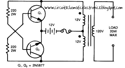
Transistor Q1 and Q2 use 2N5877 or similarity .If Q1 is faster and higher gain than Q2 , it will turn on first when aplly the input power and will hold Q2. Load current and the transformer magnetizing current the flows in the upper half of primary coil, and auto transformer supplies the base drive (two transistor) unti the transformer saturates.The transformator can use the 3A CT transformer an use the secondary coil for input and primary coil use to output, And input use the 12 volt secondary coil. Use 12 battery to power input , such as 12 V accu.
You can use the circuit at the time of death PLN electricity , using 12 volt battery or accu , you can turn n a fluorescent lamp or neon light.
Friday, December 20, 2013
Simple Inverter circuit with IC556 timer chip
This circuit is low power inverter , in this circuit only save a few components, about 9 parts. Voltage input from 10 volt to 16 volt DC into 60-Hz. And then voltage will be raised to about 115 V with power 25 W. The first section of IC 556 timer chip is wire as an astable oscilator with R2 and C1 setting the frequncy. The output is available at IC 556 pin 5. The second section is wired as a phase inverter. That output is available at IC 556 pin 9.
Schematic low inverter below :

The transformer use 120 V / 18 VCT unit that is connected backwards, so that it steps the voltage up rather than down. At resistor R3 and R4 keep output transistor Q1 and Q2 from loading the transistor. The transistor drive the transformer . The circuit can you use to supply lamp or other electronic devices.
Monday, December 16, 2013
Simple 100 Watt Inverter
This is a simplest circuit for 100 watt inverter for generating 220vAC from 12vDC. I say simplest because here in this inverter circuit a minimum number of components are used to design the schematic, which is quite difficult to make a circuit like this with further fewer components.
Simple 100 Watt Inverter Circuit Diagram

This 100W inverter circuit works great for small loads like a fan or 2-3 bulbs/lamps. In this circuit as IC1 we used a CD 4047 IC to generate 100Hz frequency (180 degree out of phase). CD 4047 IC is from Texas Instruments. It is mostly used as Astable/Monostable signal generator device. In this circuit it is triggered as astable multivibrator by the capacitor C1 between the Pin 1 and 3 of CD4047. And VR1 is used to adjust the frequency of signal.
Four 2N3055 transistors are used to amplify the pulse trains that are pre-amplified by two TIP122 transistors. There used three transistors for each side (half cycle), one TIP122 & two 2N3055 transistor to drive the output transformer (TX in circuit). Four 2N3055 transistors are used as driving transistor. An inverters maximum output power depends on two factors; one is the max current rating of transformer’s primary winding and other factor is the current rating of driver transistors.
Transformer: Use a 12v-0-12v, 10A step-down transformer in reverse. That’s mean secondary winding (12v-0-12v) will be the primary and primary winding (220VAC side) will be the secondary (output). So that it will worked like a step-up transformer. You can also use a 5A transformer instead of 10A, if you couldn’t have 10A. But the output power will decrease to 60 Watt.
+12VDC: A good quality 12V car battery could be used for DC 12V.
Parts list :
VR1 = 250K (Variable resistor/POT)
R1, R2 = 4.7K-1/4W Resistor
R3, R4, R5, R6 = 0.1R-5W
C1 = 0.022uF
C2 = 220uF-25V
D1 = BY127 Diode
D2 = 9.1V Zener Diode
Q1, Q4 = TIP122 Transistor
Q2, Q3, Q5, Q6 = 2N3055 Transistor
F1 = 10A Fuse
IC1 = CD4047
TX = 12-0-12V, 10A Step-down Transformer
VR1 = 250K (Variable resistor/POT)
R1, R2 = 4.7K-1/4W Resistor
R3, R4, R5, R6 = 0.1R-5W
C1 = 0.022uF
C2 = 220uF-25V
D1 = BY127 Diode
D2 = 9.1V Zener Diode
Q1, Q4 = TIP122 Transistor
Q2, Q3, Q5, Q6 = 2N3055 Transistor
F1 = 10A Fuse
IC1 = CD4047
TX = 12-0-12V, 10A Step-down Transformer
Thursday, November 7, 2013
6V to 220V inverter schematic
Circuit schematic above is one of the voltage inverter circuit, starting from 6-Volt input on the DC current into 220-volt AC output. For maximum output power up to 30W only, and is also very small voltage current. Input voltage plus the entrance on the transistor Q2 to provide the voltage at the collector and then go on Circumference transformer L1 and enter the base. Emitter will be merged ddengan voltage supplied L2 min. And LED1 is useful as an indicator of whether or not an inverter works especially on the transistor Q2.
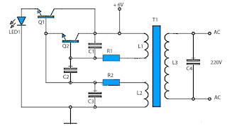
Part List :
R1 = 1K R
R2 = 220R
C1 = 10nF
C2 = 100nF
C3 = 47nF
C4 = 0,22uF 400V
Q1 = 2N5551
Q2 = C5198
LED1 use Green Led
Transformer instruction :

The above is figure from a place plastic for copper wire wrapped around, you can also use the marks that have been unused transformer. For the above number are :
1 : Place for copper wire wrapped,with a diameter of 12mm x 10mm.
2 : Hole to place an iron or ferrite rod , with diameter 10mm. 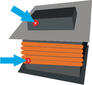
3 : Copper wire that has been rolled.
4 : Ferrite or iron rods which are mounted on the hole.
To coil L1 as much as 70 times, L2 200 times, And L3 as much as 1000 times.
L1 wire diameter 1mm
L2 wire diameter 0.8mm
L3 wire diameter 0.4 mm
4 : Ferrite or iron rods which are mounted on the hole.
To coil L1 as much as 70 times, L2 200 times, And L3 as much as 1000 times.
L1 wire diameter 1mm
L2 wire diameter 0.8mm
L3 wire diameter 0.4 mm
Sunday, October 27, 2013
6 to 12 Volt Power Supply Inverter
This inverter circuit can provide up to 800mA of 12V power from a 6V supply. For example, you could run 12V car accessories in a 6V (British?) car.
The circuit is simple, about 75% efficient and quite useful. By changing just a few components, you can also modify it for different voltages.

Part List:
R1, R4 2.2K 1/4W Resistor
R2, R3 4.7K 1/4W Resistor
R5 1K 1/4W Resistor
R6 1.5K 1/4W Resistor
R7 33K 1/4W Resistor
R8 10K 1/4W Resistor
C1,C2 0.1uF Ceramic Disc Capacitor
C3 470uF 25V Electrolytic Capcitor
D1 1N914 Diode
D2 1N4004 Diode
D3 12V 400mW Zener Diode
Q1, Q2, Q4 BC547 NPN Transistor
Q3 BD679 NPN Transistor
L1 See Notes
MISC Heatsink For Q3, Binding Posts (For Input/Output), Wire, Board
Next full text...
The circuit is simple, about 75% efficient and quite useful. By changing just a few components, you can also modify it for different voltages.
Part List:
R1, R4 2.2K 1/4W Resistor
R2, R3 4.7K 1/4W Resistor
R5 1K 1/4W Resistor
R6 1.5K 1/4W Resistor
R7 33K 1/4W Resistor
R8 10K 1/4W Resistor
C1,C2 0.1uF Ceramic Disc Capacitor
C3 470uF 25V Electrolytic Capcitor
D1 1N914 Diode
D2 1N4004 Diode
D3 12V 400mW Zener Diode
Q1, Q2, Q4 BC547 NPN Transistor
Q3 BD679 NPN Transistor
L1 See Notes
MISC Heatsink For Q3, Binding Posts (For Input/Output), Wire, Board
source:LINK
Friday, October 18, 2013
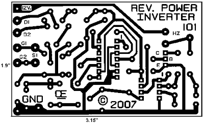
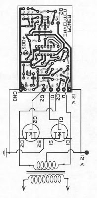
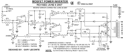
500W Mos Fet Power Inverter from 12V to 110V 220V
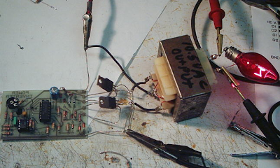
This circuit will provide a very stable "Square Wave" Output Voltage. Frequency of operation is determined by a pot and is normally set to 60 Hz. Various "off the shelf" transformers can be used. Or Custom wind your own FOR BEST RESULTS. Additional MosFets can be paralleled for higher power. It is recommended to Have a "Fuse" in the Power Line and to always have a "Load connected", while power is being applied. The Fuse should be rated at 32 volts and should be approximately 10 Amps per 100 watts of output. The Power leads must be heavy enough wire to handle this High Current Draw!
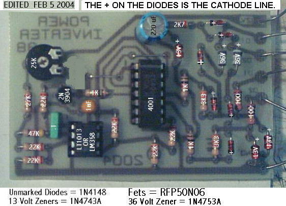
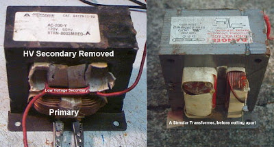
Appropriate Heat Sinks Should be used on the RFP50N06 Fets. These Fets are rated at 50 Amps and 60 Volts. ** Other types of Mosfets can be substituted if you wish. The LT1013 offers better drive that the LM358, but its your choice. The Power transformer must be capable of handling the chosen wattage output. Also, Appropriate Heat Sinks are Necessary on the Mos-Fets. Using a rebuilt Microwave transformer as shown below, it should handle about 500 watts Maximum. It requires about 18 turn Center-Tapped on the primary. To handle 500 watts would require using a 5 AWG wire. Pretty Heavy Stuff, but so is the current draw at that power.
Wednesday, October 9, 2013
12VDC to 220V AC 500W Inverter Circuit
Circuit Inverter 500 Watt 12VDC to 220VAC is made using a transistor.
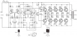
The basiccally of the circuit Inverter 12VDC to 220VAC 500 Watt This is a configuration of 2 pieces of transistors Q1 and Q2 which form a series of Flip-Flop. The output of the flip-flop Q1 and Q2 in the circuit Inverter 12VDC to 220VAC 500 Watt is then broken down for each pulse to complement each other using a series compiled by Q3 and Q4. Output which complement each other is then given to the driver transistors Q5 and Q6 form the transistor 2SC1061. Series Inverter Power Inverter from 12VDC to 220VAC 500 Watt This is a series of parallel transistors Q7 and Q8 are prepared and Q7x and Q8x the form of power with a type 2N3055 transistor 10 pieces. drawing a complete range of circuit Inverter 12VDC to 220VAC 500 Watts can be seen as follows.
Saturday, October 5, 2013
DC to AC Inverter with IC CD4047
This DC to AC inverter circuit work based on unstable multi vibrator does. In this circuit, IC CD4047 is chosen as a heart of unstable multivibrator, because this IC type gives a complementary output that has opposite phase to another ( pin 10 and 11 as seen in Figure 1), and has 50 % duty cycle that satisfy to generate a pulse for inverter.
DC to AC Inverter with IC CD4047 Circuit Diagram

DC to AC Inverter with IC CD4047 Circuit Diagram
Wednesday, October 2, 2013
12V to 220V Inverter Schematics
12V to 220V Inverter Circuit Diagrams, Even though today’s electrical appliances are increasingly often self-powered, especially the portable ones you carry around when camping or holidaying in summer, you do still sometimes need a source of 230 V AC - and while we’re about it, why not at a frequency close to that of the mains? As long as the power required from such a source remains relatively low - here we’ve chosen 30 VA - it’s very easy to build an inverter with simple, cheap components that many electronics hobbyists may even already have 12V to 220V Inverter.
 |
| 12V to 220V Inverter Circuit Diagrams |
Though it is possible to build a more powerful circuit, the complexity caused by the very heavy currents to be handled on the low-voltage side leads to circuits that would be out of place in this summer issue. Let’s not forget, for example, that just to get a meager 1 amp at 230 VAC, the battery primary side would have to handle more than 20 ADC!. The circuit diagram of 12V to 220V Inverter Schematics our project is easy to follow. A classic 555 timer chip, identified as IC1, is configured as an astable multivibrator at a frequency close to 100 Hz, which can be adjusted accurately by means of potentiometer P1.
As the mark/space ratio (duty factor) of the 555 output is a long way from being 1:1 (50%), it is used to drive a D-type flip-flop produced using a CMOS type 4013 IC. This produces perfect complementary square-wave signals (i.e. in antiphase) on its Q and Q outputs suitable for driving the output power transistors. As the output 12V to 220V Inverter current available from the CMOS 4013 is very small, Darlington power transistors are used to arrive at the necessary output current. We have chosen MJ3001s from the now defunct Motorola (only as a semi-conductor manufacturer, of course!) which are cheap and readily available, but any equivalent power Darlington could be used.
These drive a 230 V to 2 × 9 V center-tapped transformer used ‘backwards’ to produce the 230 V output. The presence of the 230 VAC voltage is indicated by a neon light, while a VDR (voltage dependent resistor) type S10K250 or S07K250 clips off the spikes and surges that may appear at the transistor switching points. The output signal this circuit produces is approximately a square wave; only approximately, since it is somewhat distorted by passing through the transformer. Fortunately, it is suitable for the majority of electrical devices it is capable of supplying, whether they be light bulbs, small motors, or power supplies for electronic devices.
PCB layout:
These drive a 230 V to 2 × 9 V center-tapped transformer used ‘backwards’ to produce the 230 V output. The presence of the 230 VAC voltage is indicated by a neon light, while a VDR (voltage dependent resistor) type S10K250 or S07K250 clips off the spikes and surges that may appear at the transistor switching points. The output signal this circuit produces is approximately a square wave; only approximately, since it is somewhat distorted by passing through the transformer. Fortunately, it is suitable for the majority of electrical devices it is capable of supplying, whether they be light bulbs, small motors, or power supplies for electronic devices.
PCB layout:

COMPONENTS LIST
Resistors
R1 = 18k?
R2 = 3k3
R3 = 1k
R4,R5 = 1k?5
R6 = VDR S10K250 (or S07K250)
P1 = 100 k potentiometer
Capacitors
C1 = 330nF
C2 = 1000 µF 25V
Semiconductor
T1,T2 = MJ3001
IC1 = 555
IC2 = 4013
Miscellaneous
LA1 = neon light 230 V
F1 = fuse, 5A
TR1 = mains transformer, 2x9V 40VA (see text)
4 solder pins
Note that, even though the circuit is intended and designed for powering by a car battery, i.e. from 12 V, the transformer is specified with a 9 V primary. But at full power you need to allow for a voltage drop of around 3 V between the collector and emitter of the power transistors. This relatively high saturation voltage is in fact a ‘shortcoming’ common to all devices in Darlington configuration, which actually consists of two transistors in one case. We’re suggesting a PCB design to make it easy to construct this project; as the component overlay shows, the PCB only carries the low-power, low-voltage components.
The Darlington transistors should be fitted onto a finned anodized aluminum heat-sink using the standard insulating accessories of mica washers and shouldered washers, as their collectors are connected to the metal cans and would otherwise be short-circuited. An output power of 30 VA implies a current consumption of the order of 3 A from the 12 V battery at the ‘primary side’. So the wires connecting the collectors of the MJ3001s [1] T1 and T2 to the transformer primary, the emitters of T1 and T2 to the battery negative terminal, and the battery positive terminal to the transformer primary will need to have a minimum cross-sectional area of 2 mm2 so as to minimize voltage drop.
The transformer can be any 230 V to 2 × 9 V type, with an E/I iron core or toroidal, rated at around 40 VA. Properly constructed on the board shown here, the circuit should work at once, the only adjustment being to set the output to a frequency of 50 Hz with P1. You should keep in minds that the frequency stability of the 555 is fairly poor by today’s standards, so you shouldn’t rely on it to drive your radio-alarm correctly – but is such a device very useful or indeed desirable to have on holiday anyway? Watch out too for the fact that the output voltage of this inverter is just as dangerous as the mains from your domestic power sockets.
So you need to apply just the same safety rules! Also, the project should be enclosed in a sturdy ABS or diecast so no parts can be touched while in operation. The circuit should not be too difficult to adapt to other mains voltages or frequencies, for example 110 V, 115 V or 127 V, 60 Hz. The AC voltage requires a transformer with a different primary voltage (which here becomes the secondary), and the frequency, some adjusting of P1 and possibly minor changes to the values of timing components R1 and C1 on the 555.
Resistors
R1 = 18k?
R2 = 3k3
R3 = 1k
R4,R5 = 1k?5
R6 = VDR S10K250 (or S07K250)
P1 = 100 k potentiometer
Capacitors
C1 = 330nF
C2 = 1000 µF 25V
Semiconductor
T1,T2 = MJ3001
IC1 = 555
IC2 = 4013
Miscellaneous
LA1 = neon light 230 V
F1 = fuse, 5A
TR1 = mains transformer, 2x9V 40VA (see text)
4 solder pins
Note that, even though the circuit is intended and designed for powering by a car battery, i.e. from 12 V, the transformer is specified with a 9 V primary. But at full power you need to allow for a voltage drop of around 3 V between the collector and emitter of the power transistors. This relatively high saturation voltage is in fact a ‘shortcoming’ common to all devices in Darlington configuration, which actually consists of two transistors in one case. We’re suggesting a PCB design to make it easy to construct this project; as the component overlay shows, the PCB only carries the low-power, low-voltage components.
The Darlington transistors should be fitted onto a finned anodized aluminum heat-sink using the standard insulating accessories of mica washers and shouldered washers, as their collectors are connected to the metal cans and would otherwise be short-circuited. An output power of 30 VA implies a current consumption of the order of 3 A from the 12 V battery at the ‘primary side’. So the wires connecting the collectors of the MJ3001s [1] T1 and T2 to the transformer primary, the emitters of T1 and T2 to the battery negative terminal, and the battery positive terminal to the transformer primary will need to have a minimum cross-sectional area of 2 mm2 so as to minimize voltage drop.
The transformer can be any 230 V to 2 × 9 V type, with an E/I iron core or toroidal, rated at around 40 VA. Properly constructed on the board shown here, the circuit should work at once, the only adjustment being to set the output to a frequency of 50 Hz with P1. You should keep in minds that the frequency stability of the 555 is fairly poor by today’s standards, so you shouldn’t rely on it to drive your radio-alarm correctly – but is such a device very useful or indeed desirable to have on holiday anyway? Watch out too for the fact that the output voltage of this inverter is just as dangerous as the mains from your domestic power sockets.
So you need to apply just the same safety rules! Also, the project should be enclosed in a sturdy ABS or diecast so no parts can be touched while in operation. The circuit should not be too difficult to adapt to other mains voltages or frequencies, for example 110 V, 115 V or 127 V, 60 Hz. The AC voltage requires a transformer with a different primary voltage (which here becomes the secondary), and the frequency, some adjusting of P1 and possibly minor changes to the values of timing components R1 and C1 on the 555.
B. Broussas
Source : Link
Another interesting related Circuit : DC 12V to 24V Contverter, 5000W PWM inverter, and other Inverter / Converter Circuit.
Another interesting related Circuit : DC 12V to 24V Contverter, 5000W PWM inverter, and other Inverter / Converter Circuit.
Subscribe to:
Posts (Atom)