Showing posts with label output. Show all posts
Showing posts with label output. Show all posts
Sunday, January 12, 2014
Inverter 12V to 115V with 25 W power output
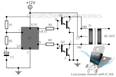
Low power inverter schematic are only use 9 components , one of which IC 556 , TIP120 NPN Darlington transistor.And turns 10 to 16 Vdc into 60 HZ, output 115 V square-wave power to operate ac equipment up to 25 W. In the circuit first ic originally hires as a timer chip m for stabilizatiom oscilator with components R1 and C1 setting frequency oscilator. Then the two transistor driver, drive the transformer push-pull fashion, When one transistor is biased on , the other circuit cut-off . The transformer is a 120V/18Vct unit that is connected backwards, so that it steps the voltage up rather than down. Oscilator circuit operates from about 4 to 16 V for stable output.
Part List :
R1 = 1K
R2 = 12K
R3 = 1K
R4 = 1/4W
C1 = 1uF
IC = 556
Q1 = TIP120
Q2 = TIP120
T1 = 120V 18VCT

Thursday, January 9, 2014
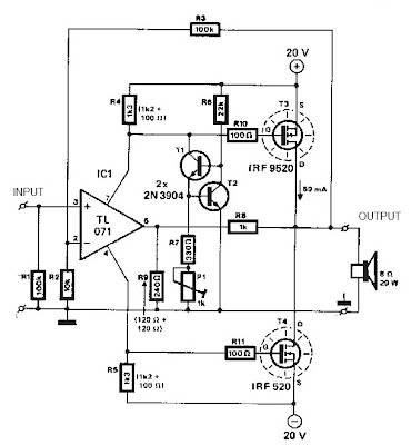
Mosfet Amplifier 20Watt Output Power
This audio amplifier showed in this circuit diagram , is a very simple and efficiency audio amplifier circuit based on the TDA1308 integrated class-AB stereo headphone . The device is fabricated in a 1 mm Complementary Metal Oxide Semiconductor (CMOS) process and has been primarily developed for portable digital audio applications.
You can use this circuit diagram with TDA1308 or TDA1308A , the difference between the TDA1308 and the TDA1308A is that the TDA1308A can be used at low supply voltages. The maximum output power that can be obtained with this circuit is around 80mwatts. This audio amplifier circuit requires a very low voltage power supply : from 3 to 7 volts for single supply or 1.5 to 3 volts for dual supply , for TDA1308 .
The TDA1308A supports a low voltage input down to 1.2 volts , but the typical power supply required for both circuits is 5 volts for single supply and 2.5 volts for dual supply .
As you can see the circuit requires very few external components and can be configured to work in stereo or mono configuration.
Tuesday, November 19, 2013
9V output switching power supply
By using the circuit you do not bother to roll up a transformer that is used to reduce voltage AC 220V to 7V ,9 V or 12V, etc. When using a large transformer we will find it hard to make transformator. by rolling hundreds or even thousands of times roll. But if you use this circuit a little just enough to roll trafo not to small, and its be relatively small.

R1________________________________680K
R2________________________________47K
R3________________________________100R
R4________________________________1K
R5________________________________1R
D1,D2,D3,D4,D7,D8,D9,D10__________1N4007
D5,D6_____________________________1N4148
C1________________________________2u2F 400V
C2________________________________2n2
C3________________________________47uF 25V
C4________________________________10n
C5________________________________470uF / 16V
Q1________________________________MJE13003
Q2________________________________S8050
This is construction of transformer. For the first toll 220 times , then after that wrap right on top of L2 , and L3 on L2.

Wednesday, November 13, 2013
Power Supply with regulator output use IC uA723
This circuit operating with IC uA723 and add amplified with transistor TIP31 or similiar transistor with TIP31 . Input voltage for circuit about 10 - 40 volt DC , formerly of AC voltage 220 volts or 110 volts , then lowered by the transformer voltage to 30 volts. And the supply output voltage from 1 volt to 35 volt DC you can adjust it on potentiometer R2.
See this circuit power supply below :

Output voltage transformer used 10 to 40 Volts . On resistor Rsc is the current limit set resistor. Its value is calculated as :
Rsc = 0.65 Volt For Example : If you need current output 2.0 A
Rsc = 0.65 / 2.0 = 0.32 Ohm So , you must use 0.32 Ohm to current output 2.0 A
Monday, October 14, 2013
Charger circuit equipped with a regulator circuit output voltage
The circuit charger is equipped with voltage output settings , so that we can regulate how much voltage to charge the battery. And the settings using the potentio making it easier for us managing voltage up to a mV. See charger circuit below :

Adjust the circuit by setting the 500 Ohm resistor while it is attached to a fully charged battery.
You can use the circuit to charge :
- Cells battery
- Wet Accu
- Dry Accu
- Nicad battery
- Solar battery
Friday, October 4, 2013
5V 10A output switching power supply
The Schematic above shows a 10A power suplly with a 5V output and with power 50W. It is a flyback converter operating in the continuous mode. The circuit features a primary side and secondary side controller with full protection from fault conditions such as overcurrent. After the fault condition has been removed the power supply will enter the soft start cycle before recomming normal operation.

Resistor
R1_____100Ω
R2_____1Ω 1W
R3_____10Ω
R4_____100KΩ
R5_____0.33Ω 1W
R6_____10KΩ
R7_____390Ω
R8_____22KΩ
R9_____68Ω
R10____10Ω
R11____3.3Ω
RL_____5Ω 10W
Capacitor
C1_____0.022uF 400V
C2_____470uF 250V
C3_____470uF
C4_____220pF
C5_____470pF
C6_____2200pF
C7_____270pF
C8_____39pF
C9_____11,000uF
C10____10uF
C11____0.047uF
Diode
D1____1N4937
D2____MBR1035
M1____Diode Bridge
Inductor , Transformator
L1_____25uH
T1_____Lp - 9 mH = 1 : 15
T2_____50 uH. n = 1: 3
Transistor
Q1____BUZ80A
Q2____GE IRF823
Saturday, September 21, 2013
Multiple output switching power supply circuit
This power supply uses two VN400A 400 Volts MOSFETs in a half-bridge power switch configuration. Each output consists of +5V at 20 A and 15 V at 1 A . Three-terminal regulators are used for the low-currents outputs , either 12 Volts or 15 Volts can be made available with a simple change in the transformer secondary windings. Schematic diagram below :

IC TL494 switching regulator IC provides pulse-with modulation control and drive signals for the power supply , The upper MOSFET , Q7 , in the power switch stage is driven by a simple transformer drive circuit. The lower MOSFET , Q6 , since it ground referenced , is directly driven from the control IC.
Subscribe to:
Posts (Atom)