Showing posts with label timer. Show all posts
Showing posts with label timer. Show all posts
Thursday, December 26, 2013
00 To 99 Minute Timer Using PIC16F628A Microcontroller
his might be a good practice project for beginners who just started learning embedded electronics. It is about making a very basic programmable digital timer using a PIC16F628A microcontroller. The timer duration can be set from 0-99 minutes.
As I mentioned earlier, the microcontroller used in this project is PIC16F628A running at 4.0 MHz clock using an external crystal. An HD44780 based 16×2 character LCD is the main display unit of the project where you can watch and set the timer duration using tact switch inputs. There are three tact switches connected to RB0 (Start/Stop), RB1 (Unit), and RB2 (Ten) pins. You can select the timer interval from 0-99 min using Unit and Ten minute switches. The Start/Stop switch is for toggling the timer ON and OFF. When the timer gets ON, a logic high signal appears on the RA3 pin, which can be used to switch on a Relay. The circuit diagram of this project is described below.

When the device is powered ON, the microcontroller initializes the LCD display and shows the following message. The timer is initially OFF and so does the LED or relay, whichever is connected to RA3 pin. You can set time duration between 00-99 min (in step of 1 min) using the Unit and Ten tact switches. Each switch press will increment the corresponding time digit.
When the desired time is set, press the Start/Stop switch to turn ON the timer. The RA3 pin goes high (LED glows) and the count down begins. When the timer is ON, the remaining time is also shown on the LCD screen. When the time elapsed, the timer stops and the LED turns OFF. You can interrupt and stop the timer at anytime by pressing the Start/Stop switch once more. The firmware for PIC is developed using mikroC Pro for PIC compiler. The use of Timers are avoided for simplicity. The time delays are created using the Delay_ms() function of mikroC, which seems to give reasonably accurate timing delays.
Download Mikroc Source Code And HEX File

As I mentioned earlier, the microcontroller used in this project is PIC16F628A running at 4.0 MHz clock using an external crystal. An HD44780 based 16×2 character LCD is the main display unit of the project where you can watch and set the timer duration using tact switch inputs. There are three tact switches connected to RB0 (Start/Stop), RB1 (Unit), and RB2 (Ten) pins. You can select the timer interval from 0-99 min using Unit and Ten minute switches. The Start/Stop switch is for toggling the timer ON and OFF. When the timer gets ON, a logic high signal appears on the RA3 pin, which can be used to switch on a Relay. The circuit diagram of this project is described below.
When the desired time is set, press the Start/Stop switch to turn ON the timer. The RA3 pin goes high (LED glows) and the count down begins. When the timer is ON, the remaining time is also shown on the LCD screen. When the time elapsed, the timer stops and the LED turns OFF. You can interrupt and stop the timer at anytime by pressing the Start/Stop switch once more. The firmware for PIC is developed using mikroC Pro for PIC compiler. The use of Timers are avoided for simplicity. The time delays are created using the Delay_ms() function of mikroC, which seems to give reasonably accurate timing delays.
Download Mikroc Source Code And HEX File

Saturday, December 21, 2013
LED Flasher Circuit Using 555 Timer IC
This is a simple LED flasher project that uses a common 555 timer IC for its operation. It is configured as an astable mode which means that its output is a square wave oscillator. Two LEDs are connected to its output in such a way that when one LED is ON, the other LED will turn OFF.
It uses only 10 simple parts that are easily available at any electronic shops. Capacitor C2 charges exponentially through resistors R1, R2 and the resistance of the trimpot. When C2 has charged to about 2/3 VCC it stops charging and it discharges to about 1/3 VCC through R2 and the trimpot resistance via pin 7. This is the standard operation of a 555 timer. When a Vcc of 5 V to 15 V DC is applied to the circuit, the LED will start to flash.

The frequency of the flashing can be changed by varying the resistance of the potentiometer or trimpot. Parts List The parts list of the simple LED project is as shown below.

Friday, December 20, 2013
Simple Inverter circuit with IC556 timer chip
This circuit is low power inverter , in this circuit only save a few components, about 9 parts. Voltage input from 10 volt to 16 volt DC into 60-Hz. And then voltage will be raised to about 115 V with power 25 W. The first section of IC 556 timer chip is wire as an astable oscilator with R2 and C1 setting the frequncy. The output is available at IC 556 pin 5. The second section is wired as a phase inverter. That output is available at IC 556 pin 9.
Schematic low inverter below :

The transformer use 120 V / 18 VCT unit that is connected backwards, so that it steps the voltage up rather than down. At resistor R3 and R4 keep output transistor Q1 and Q2 from loading the transistor. The transistor drive the transformer . The circuit can you use to supply lamp or other electronic devices.
Thursday, December 19, 2013
LED Circuit with Timer 555
This circuit LED reproduces the first LED sequence at this time used by FISA on behalf of Formula single racing. It may perhaps be alive used with slot car sets (such for example HO shin up AFX/Life Like/Tyco sets) or else means of communication controlled cars. IC1, a 555 timer IC, is used as a watch pulse generator. Its output is fed via NAND gates IC2a and IC2c to IC3, a 4024 binary counter. IC2b inverts the O4 output of 4024 binary counter IC3. originally, IC3 is reset and all its outputs are low, together with O4, which causes IC2b to present-day a rational climax to the pin 8 input of IC2c which after that passes pulses from the 555 timer circuit to the clock input of the 4024. IC3 then begins together with.

Following the count has reached binary 1111, the subsequently pulse sends the O4 output of IC3 high, which disables IC2c and IC3 stops with. The four used outputs of IC3 are connected to a resistor ‘ladder’ which acts to the same degree a clear-cut digital to analog convert-er (DAC). As the count increases so does the voltage produced by the side of the top of the ladder and this is connected to the inverting inputs of four comparators inside IC4 (an LM339) and to IC5, which is a 741 op amp furthermore connected while a comparator.
The categorical inputs of the comparators are connected to the taps of a voltage dividing wall, with the drumming voltages settle on using VR1, a 100kO trimpot. As IC3 counts, the rising stepped voltage from the DAC ladder switches the comparators on clothed in sequence, preliminary with IC4d and working up to IC5. in the same way as both comparator is curved on, its pair off of LEDs is lit; former LEDs 1 & 2, next LEDs 3 & 4 and so on. as soon as all five pairs of LEDs are lit, the then pulse from IC1 moves the binary count of IC3 to 10000, so the DAC voltage drops back to zilch and all LEDs are extinguished. by the same spell, with too stops, for the reason that the area of high pressure on O4 causes IC2c to check extra gate pulses. The circuit in that case remains reserve until the counter is reset by urgent pushbutton switch S1. This allows a recent sequence to initiate.
Tuesday, December 17, 2013
Running Light circuit uses a CMOS 555 timer
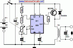
A Transcutaneous Electrical Nerve Stimulation (TENS) device is, put bluntly, a machine for giving electric shocks. The author was prescribed such a device on loan by his orthopaedic specialist. The unit has a large number of programmes, of which he used only one. Measuring the signals at the output of the device in this mode revealed damped oscillations at a frequency of approximately 2.5 kHz, with a repetition rate of approximately 100 Hz.
 |
| Running Light circuit uses a CMOS 555 timer |
How hard can it be to make such a device ourselves? The simple circuit uses a CMOS 555 timer to produce a brief pulse which feeds a 1:10 miniature transformer. Together with a 4.7 nF capacitor the transformer makes a parallel resonant circuit: the resonance leads to a considerable increase in the output voltage. The pulse width can be adjusted using a potentiometer, here shown combined with the on-off switch. Wider pulses produce higher output voltages. Since a peak voltage of up to 200 V can be produced, the transformer must have adequate insulation: Conrad Electronics type 516260-62 is suitable. A low-cost phono socket at the output gives reliable connection to the electrode cable.
The adhesive electrodes shown in the photograph (disposable and permanent types are available) can be obtained from pharmacies and medical suppliers. They generally have connectors compatible with 2 mm banana plugs, and so it is possible to make up the necessary cable yourself. To treat responsive parts of the body, such as the arm, the potentiometer need not be turned up far to obtain the necessary sensation. Less sensitive parts, such as the knee or foot, need a rather higher voltage and hence a correspondingly higher potentiometer setting.
Author: Klaus Rohwer – Copyright: Elektor Electronics Magazine
Link:http://www.extremecircuits.net/2010/06/transcutaneous-electrical-nerve_03.html
Friday, November 15, 2013
Transistor Checker with 555 Timer 4027IC
This regular circuit has helped me prohibited on many occasions. It is able to check transistors, inside the circuit, down to 40 ohms across the radio dish-foot otherwise base-emitter junctions. It can in addition check the output power transistors on amplifier circuits. Circuit company is because follows. The 555 timer ( IC1 ) is usual up as a 12hz multi vibrator. The output on pin 3 drives the 4027 flip-dud ( IC2). This flip-flop divides the input frequency by two and delivers complementary voltage outputs to pin 15 and 14. The outputs are connected to LED1 and LED2 through the current limiting resistor R3.

The LEDs are arranged so to facilitate what time the polarity across the circuit is lone way single one LED force light and what time the polarity reverses the other LED will light, therefore while rebuff transistor is connected to the tester the LEDs will alternately flicker. The IC2 outputs are too connected to resistors R4 and R5 with the junction of these two resistors connected to the immoral of the transistor being tested. With a proficient transistor connected to the tester, the transistor yearn for circle on and crop a passing across the LED duo. If a good NPN transistor is connected next LED1 will burst by itself and if a good PNP transistor is connected then LED2 will flash by itself. If the transistor is initiate both LEDs force flash and if the transistor is shorted at that moment neither LED will flash.
Tuesday, November 12, 2013
PWM controller with 555 timer chip

IC Timer 555 has a basic PWM controller with pulse width control feature 0 .. 100% which is controlled using the R1, at the time of controlling the oscillator frequency relatively stabi so it may be used to build the Simple PWM controller.
Frequency of Simple PWM controller 555 depending on the value of R1 and C1, values shown R1 and C1 will form the output with a frequency of 170 to 200 Hz. Diode-diode used in the Simple PWM controller With this 555 can use a 1N4148.
R2, R3 and C3 form a giver triger circuit beginning at the reset IC 555 for 2 seconds. If you want to use a series of Simple PWM controller 555 with the V + not +12 V, it does not matter to raise tilapia R2 where (V + * R2) / (R2 + R3) is about 2, because it limits the signal level reset is 0.5 .. 1V. If you do not do that, then signal the kickstart to get too close to the limit reset signal reception.
 |
| PWM controller circuit |
Q output of 555 on the Simple PWM controller circuit 555 is used for driver PWM pulse, so that the discharge pin is used for transistor output driver instead. This is an open collector output, and is used as an active signal is low, so it can work. D3 protects the output transistor of the load induction. You may replace any suitable transistors for Q1, BD140 is 1.5 amps.
C4 and C5 is the power decoupling capacitor for the IC 555 on the Simple PWM controller circuit 555, which produce relatively large level of push-pull output stage.
Friday, November 1, 2013
555 Timer for DC to DC Converter Circuit
 |
| 555 Timer for DC to DC Converter |
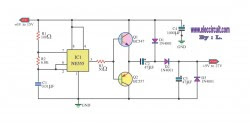
This circuit is called DC TO DC converter circuit.Which increase the voltage circuit.There can be customized to change the output values. When the power supply input to IC1 is the output pin 3 at a frequency of 1 kHz.The frequency is Q1 and Q2, which will continue to use push pool work interchangeably.If this is the positive output signal Q1 Q2 will run the delete function this reason, C2 and C3 capacitors are half-wave alternating.When to use. Voltage from C2 to C3 is discharged out to the input voltage over almost two times less than 2 times due to the loss of diodes D1-D3.
Monday, October 21, 2013
PIC Digital Clock Timer
his clock timer uses a PIC16F628 microcontroller to display 3 and 1/2 digit time and control an external load. The clock includes a calendar with leap year and optional daylight savings adjustments. The timer output can be set from 1 to 59 minutes and manually switched on and off. The clock also has a correction feature that allows an additional second to be added every so many hours to compensate for a slightly slow running oscillator. The oscillator uses a common 32.768 KHz watch crystal and the frequency can be adjusted slightly with the 24pF capacitor on the right side of the crystal.
There are 7 displays that advance each time the D switch is toggled. To make adjustments, set the RA5 switch to the "B" position and then toggle the E and F switches to advance the data in the hours or minutes digits. Then toggle the "D" switch to move to the next data. After the 7th display, it will go back to the top and display the current time. Or, just press the time switch C to get to the top at anytime. When done setting everything up, set the RA5 switch to the "A" position so the data cannot be accendentally changed. You can still view everything with the "D" advance key, but the E an F switches will just turn on or off the alarm at RB7. I use it with an external transistor to switch on and off a radio.
PIC Digital Clock Timer Circuit Diagram

The Daylight savings setting (in the 6th display in the minutes digits) is used to enable daylight savings time adjustments, one hour ahead on the 2nd sunday in March, and one hour behind on the first sunday in November. The entry will be either 0, 1, or 3.
0 = Daylight savings time disabled (default).
1 = Savings time enabled and current time is standard time.
3 = Savings time enabled and current time is daylight savings time.
The last 2 entries on the list (Year and Correction) is for the current year (1 to 4) (4 = Leapyear) so todays setting (2006) will be 2 since leapyear will be on year 4 which is 2 years from now. The correction setting will add a second every so many hours for fine adjustment to the oscillator frequency. My setting is 18 which adds a second every 18 hours. Its pretty accurate and only loses 3 seconds a month. You probably want to run it for a couple weeks to figure out what correction is needed for the crystal you have.
Switch functions:
RA0 (C switch) = Display Time
RA1 (D switch) = Advance to next data (alarm, calendar, etc)
RA2, RA3 (E and F switch) = Advance hours and minutes (in setup mode).
RA2, RA3 (E and F switch) = Toggle alarm output on/off (in run mode)
RA5 in the B position (open) = Setup Mode
Download asm file
There are 7 displays that advance each time the D switch is toggled. To make adjustments, set the RA5 switch to the "B" position and then toggle the E and F switches to advance the data in the hours or minutes digits. Then toggle the "D" switch to move to the next data. After the 7th display, it will go back to the top and display the current time. Or, just press the time switch C to get to the top at anytime. When done setting everything up, set the RA5 switch to the "A" position so the data cannot be accendentally changed. You can still view everything with the "D" advance key, but the E an F switches will just turn on or off the alarm at RB7. I use it with an external transistor to switch on and off a radio.
PIC Digital Clock Timer Circuit Diagram
0 = Daylight savings time disabled (default).
1 = Savings time enabled and current time is standard time.
3 = Savings time enabled and current time is daylight savings time.
The last 2 entries on the list (Year and Correction) is for the current year (1 to 4) (4 = Leapyear) so todays setting (2006) will be 2 since leapyear will be on year 4 which is 2 years from now. The correction setting will add a second every so many hours for fine adjustment to the oscillator frequency. My setting is 18 which adds a second every 18 hours. Its pretty accurate and only loses 3 seconds a month. You probably want to run it for a couple weeks to figure out what correction is needed for the crystal you have.
Switch functions:
RA0 (C switch) = Display Time
RA1 (D switch) = Advance to next data (alarm, calendar, etc)
RA2, RA3 (E and F switch) = Advance hours and minutes (in setup mode).
RA2, RA3 (E and F switch) = Toggle alarm output on/off (in run mode)
RA5 in the B position (open) = Setup Mode
Download asm file
Tuesday, October 1, 2013
Timer with about 10 minutes
Applications of 555 timer IC is very diverse, one series of 10 Minute Timer with IC 555. 10 Minute Timer This circuit uses IC NE555 is set as a monostable multivibrator. The timing of the timer circuit 10 minutes with the IC 555 is governed by the configuration of C2, R4 and R5. The greater the value of C2 at 10-minute timer circuit with IC 555 timer is active then the time will stay longer.
Total resistance value between R4 and R5 also determine the active circuit 10 minute timer with IC 555, where the greater the value the longer time was also active. The core active setting the timer on the set of C2 charging time for 10 minutes on the timer circuit with IC 555. So, with the value of C2 remain so with time on the circuit timing Timer 10 minutes by IC 555 can be set by changing the resistance value R 4 + R 5. Indicators of active timer at 10 minute timer circuit with IC 555 uses the LED D2 and D3 will light up only one course to identify the active timer and the timer has not been met.
Figure 10 Minute Timer circuit with IC 555

Description:
S1 is used to set / reset timer
R5 is used to set the timer to the desired time
Thursday, September 26, 2013
9 Sec Timer with LED Indication and Control Relay
The electronic circuit provides a visual time 9 second delay using ten LED before control by closing a 12 Vdc relay. That the reset switch has closed, IC 4017 decade counter will be reset to zero count which illuminates the LED driven from pin 3. IC 555 timer output at pin 3 will be high and the voltage at pins 6 and 2 of the timer will be a little less than the lower trigger point, or about 3 Vdc.
9 Sec Timer with LED Indication and Control Relay Circuit Schematic

That time the switch is opened, the transistor in parallel with the timing capacitor (22uF) is shut off allowing the capacitor to begin charging and the IC 555 timer circuit to produce an approximate one second clock signal to the decade counter. The counter advances on each positive going change at pin 14 and is enabled with pin 13 terminated low. When the 9th count is reached, pin 11 and 13 will be high, stopping the counter and energizing the relay. Longer delay times can be obtained with most capacitor or most resistor at pins 2 and 6 of the IC 555 timer.
9 Sec Timer with LED Indication and Control Relay Circuit Schematic
Subscribe to:
Posts (Atom)