Showing posts with label relay. Show all posts
Showing posts with label relay. Show all posts
Monday, January 27, 2014
Parallel Port Relay Interface
Below are three examples of controlling a relay from the PCs parallel printer port (LPT1 or LPT2). Figure A shows a solid state relay controlled by one of the parallel port data lines (D0-D7) using a 300 ohm resistor and 5 volt power source. The solid state relay will energize when a "0" is written to the data line. Figure B and C show mechanical relays controlled by two transistors. The relay in figure B is energized when a "1" is written to the data line and the relay in figure C is energized by writing a "0" to the line. In each of the three circuits, a common connection is made from the negative side of the power supply to one of the port ground pins (18-25).
Parallel Port Relay Interface Schematic
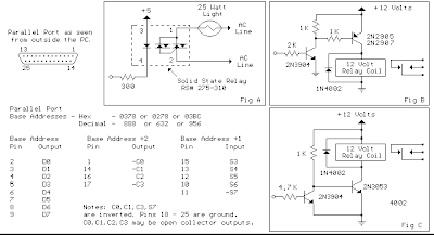
There are three possible base addresses for the parallel port You may need to try all three base addresses to determine the correct address for the port you are using but LPT1 is usually at Hex 0378. The QBasic "OUT" command can be used to send data to the port. OUT, &H0378,0 sets D0-D7 low and OUT, &H378,255 sets D0-D7 high. The parallel port also provides four control lines (C0,C1,C2,C3) that can be set high or low by writing data to the base address+2 so if the base address is Hex 0378 then the address of the control latch would be Hex 037A. Note that three of the control bits are inverted so writing a "0" to the control latch will set C0,C1,C3 high and C2 low.
Parallel Port Relay Interface Schematic
There are three possible base addresses for the parallel port You may need to try all three base addresses to determine the correct address for the port you are using but LPT1 is usually at Hex 0378. The QBasic "OUT" command can be used to send data to the port. OUT, &H0378,0 sets D0-D7 low and OUT, &H378,255 sets D0-D7 high. The parallel port also provides four control lines (C0,C1,C2,C3) that can be set high or low by writing data to the base address+2 so if the base address is Hex 0378 then the address of the control latch would be Hex 037A. Note that three of the control bits are inverted so writing a "0" to the control latch will set C0,C1,C3 high and C2 low.

Wednesday, December 18, 2013
8 Relay Control Circuit
8 Relay Control Circuit
R1-8=4.7 Kohms T1-8= BD139 (R1-8=15 Kohms if T1-8=BD679)
RL1-8=6V-24V dc Relay D1-8=1N4148

Next full text...
R1-8=4.7 Kohms T1-8= BD139 (R1-8=15 Kohms if T1-8=BD679)
RL1-8=6V-24V dc Relay D1-8=1N4148
Monday, December 16, 2013
Photo Sensor Control Relay
A photo or slightly activated relay normally open relay in the closed circuit / contact with the light. In this circuit, a photodiode is used to sense light. The photodiode has a high resistance in the absence of light strikes. The photodiode is connected to the reverse biased state. The only current flowing through it will be due to minority carriers.
Photo Sensor Control Relay Circuit Diagram
 When light falls on it, the minority current carriers in the wake of increasing the diode provides a low resistance. Because the voltage across the diode will not be sufficient to bias transistor Q1 and will be reset. Where there is darkness, the resistance increases photodiode and the voltage across it will be enough to move forward bias the transistor Q1 of the relay ON. The diode D2 is used as a diode to protect transistor switching transients produced relay. In this way, the load on the relay contacts can be switched on and off using light strikes the photodiode.
Photo Sensor Control Relay Circuit Diagram
Saturday, November 2, 2013
Single Transistor Relay Toggle
The circuit below requires a double pole, double throw relay in conjunction with a single transistor to allow toggling the relay with a momentary push button. One set of relay contacts is used to control the load, while the other is used to provide feedback to keep the relay activated or deactivated. Several push buttons can be wired in parallel to allow toggling the relay from different locations.
In the deactivated state, the relay contacts are arranged so the 1000 uF capacitor will charge to about 2.7 volts. When the switch is closed, the capacitor voltage is applied to the transistor base through a 560 resistor causing the transistor to turn on and activate the relay. In the activated state, the relay contacts are arranged so the 3.3K resistor and 560 ohm resistor provide a continous current to the transistor base maintaining the activated state. While in the activated state, the capacitor is allowed to discharge to zero through the 1K resistor. When the switch is again closed, the capacitor will cause the transistor base to move toward ground deactivating the relay.
Single Transistor Relay Toggle Circuit Diagram
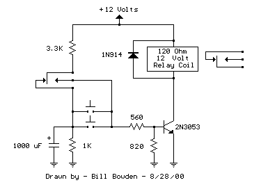
The circuit has three distinct advantages, it requires only a few parts, always comes up with the relay deactivated, and doesnt need any switch debouncing. However since the capacitor will begin charging as soon as the button is depressed, the button cannot remain depressed too long to avoid re-engaging the relay. This problem can be minimized with an additional resistor connected from the transistor base to ground so that the base voltage is close to 0.7 volts with the button depressed and the transistor is biased in the linear region. With the button held down, the relay coil voltage should be somewhere between the pull in and drop out voltages so that the relay will maintain the last toggled state.
This worked out to about 820 ohms for the circuit I built using a 12 volt, 120 ohm relay coil and 2N3053 transistor. Temperature changes will effect the situation but the operation is still greatly improved. I heated the transistor with a hair dryer and found that the relay will re-engage with the button held down for approximately 1 second, but this is not much of a problem under normal operation.
In the deactivated state, the relay contacts are arranged so the 1000 uF capacitor will charge to about 2.7 volts. When the switch is closed, the capacitor voltage is applied to the transistor base through a 560 resistor causing the transistor to turn on and activate the relay. In the activated state, the relay contacts are arranged so the 3.3K resistor and 560 ohm resistor provide a continous current to the transistor base maintaining the activated state. While in the activated state, the capacitor is allowed to discharge to zero through the 1K resistor. When the switch is again closed, the capacitor will cause the transistor base to move toward ground deactivating the relay.
Single Transistor Relay Toggle Circuit Diagram
The circuit has three distinct advantages, it requires only a few parts, always comes up with the relay deactivated, and doesnt need any switch debouncing. However since the capacitor will begin charging as soon as the button is depressed, the button cannot remain depressed too long to avoid re-engaging the relay. This problem can be minimized with an additional resistor connected from the transistor base to ground so that the base voltage is close to 0.7 volts with the button depressed and the transistor is biased in the linear region. With the button held down, the relay coil voltage should be somewhere between the pull in and drop out voltages so that the relay will maintain the last toggled state.
This worked out to about 820 ohms for the circuit I built using a 12 volt, 120 ohm relay coil and 2N3053 transistor. Temperature changes will effect the situation but the operation is still greatly improved. I heated the transistor with a hair dryer and found that the relay will re-engage with the button held down for approximately 1 second, but this is not much of a problem under normal operation.
Thursday, September 26, 2013
9 Sec Timer with LED Indication and Control Relay
The electronic circuit provides a visual time 9 second delay using ten LED before control by closing a 12 Vdc relay. That the reset switch has closed, IC 4017 decade counter will be reset to zero count which illuminates the LED driven from pin 3. IC 555 timer output at pin 3 will be high and the voltage at pins 6 and 2 of the timer will be a little less than the lower trigger point, or about 3 Vdc.
9 Sec Timer with LED Indication and Control Relay Circuit Schematic

That time the switch is opened, the transistor in parallel with the timing capacitor (22uF) is shut off allowing the capacitor to begin charging and the IC 555 timer circuit to produce an approximate one second clock signal to the decade counter. The counter advances on each positive going change at pin 14 and is enabled with pin 13 terminated low. When the 9th count is reached, pin 11 and 13 will be high, stopping the counter and energizing the relay. Longer delay times can be obtained with most capacitor or most resistor at pins 2 and 6 of the IC 555 timer.
9 Sec Timer with LED Indication and Control Relay Circuit Schematic
Subscribe to:
Posts (Atom)