Showing posts with label volt. Show all posts
Showing posts with label volt. Show all posts
Saturday, October 18, 2014
Eliminator 1 5 Volt battery using LM317
This circuit is a battery eliminator 1.5 V, that is, a power supply of 1.5 volts, low consumption that takes as input the output of the USB PC or notebook. The power adapter is simple, it converts the voltage from 5V to 1.5V USB ports, using the popular LM317 IC and a few other components. To be exact this circuit uses only three components, one is the LM317, R1 = R2 = 470 ohm and 100 ohm.
Eliminator 1.5 Volt battery using LM317 Circuit Diagram


Friday, January 24, 2014
5 Volt Switching Regulator Power Supply
The switching regulator power supply used LM2575-5.0 on this schematic.
You can make the stable voltage by using the 3 terminal regulator like LM317. However, because the output electric current and the inputted electric current are the same approximately, the difference between the input electric power (The input voltage x The input electric current) and the output power (The output voltage x The output current) is consumed as the heat with the regulator. Because it is, the efficiency isn�t good.
You can make the stable voltage by using the 3 terminal regulator like LM317. However, because the output electric current and the inputted electric current are the same approximately, the difference between the input electric power (The input voltage x The input electric current) and the output power (The output voltage x The output current) is consumed as the heat with the regulator. Because it is, the efficiency isn�t good.
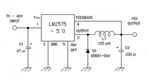
Data sheet for LM2575
SIMPLE SWITCHER 1A Step-Down Voltage Regulator
http://www.national.com/pf/LM/LM2575.htm
Sunday, December 22, 2013
12 Volt Nicad Battery charger
See this charger schematic below :

Tuesday, December 17, 2013
12 Volt Battery charger and also can Accu Charger
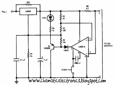
This 12 Volt Battery charger circuit best performance to charger 12 volt battery . Why this charger is best performance because this 12 Volt Battery charger quickly to recharger battery and shuts off at full charge. Initially , charging current is limited 2 A , but you can change for the transistor. As the battery voltage rises , current to the battery decreases , and when the current has decreases to 150 mA or 0.15 A this 12 Volt Battery charger switches to a lower float voltage , which prevents overcharge.
 |
| 12 Volt Battery charger Click to view Enlarge |
The 12 Volt Battery charger can be charger wet accu and dry accu , and to be make the accu old last longer. The output charger goes to 14.5 Volt. As the battery or accu approaches full charge , the charging current decreases and the output voltage is reduced from 14.5 Volt to about 12.5 volt, terminating the charging.
Wednesday, November 20, 2013
16 × 2 LCD Volt Meter Ampere Meter With PIC
Volt meters & ampere meter with PIC can be used to measure voltage and current simultaneously. The series of volt meters & ampere meter with PIC16F876A PIC is used as a data processor voltage and current are measured.
This circuit uses the viewer in the form of 16 × 2 LCD used for the data display voltage and current measurements. In the article volt meter and ampere meter with PIC are discussed kerannya limited to devices only. More detail can be seen from the image sequence volt meter and ampere meter with PIC below.
The images of Volt Meter & Ampere Meter With PIC Circuit
 |
| Volt meters & ampere meter with PIC |
Friday, November 1, 2013
6 18 Volt audio power amplifier
This time I will post about the audio amplifier based on IC KA2204. In an audio amplifier circuit has a power output that can also be referred to as a low-grade resources that have only 6 Watts output with 4 Ohm impedance. Frequency response 30 Hz to 18 kHz . For the scheme can be seen below.
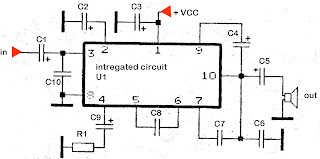
Supply voltage and a maximum of at least 6 Volt to 18 Volt
Part List
R1 = 56R
C1 = 1uF
C2 = 220uF
C3 = 100uF
C4 = 47uF
C5 = 1000uF
C6 = 100nF
C7 = 470pF
C1 = 1uF
C2 = 220uF
C3 = 100uF
C4 = 47uF
C5 = 1000uF
C6 = 100nF
C7 = 470pF
C8 = 22pF
C9 = 47uF
C10 = 47pF
C10 = 47pF
Sunday, October 27, 2013
6 to 12 Volt Power Supply Inverter
This inverter circuit can provide up to 800mA of 12V power from a 6V supply. For example, you could run 12V car accessories in a 6V (British?) car.
The circuit is simple, about 75% efficient and quite useful. By changing just a few components, you can also modify it for different voltages.

Part List:
R1, R4 2.2K 1/4W Resistor
R2, R3 4.7K 1/4W Resistor
R5 1K 1/4W Resistor
R6 1.5K 1/4W Resistor
R7 33K 1/4W Resistor
R8 10K 1/4W Resistor
C1,C2 0.1uF Ceramic Disc Capacitor
C3 470uF 25V Electrolytic Capcitor
D1 1N914 Diode
D2 1N4004 Diode
D3 12V 400mW Zener Diode
Q1, Q2, Q4 BC547 NPN Transistor
Q3 BD679 NPN Transistor
L1 See Notes
MISC Heatsink For Q3, Binding Posts (For Input/Output), Wire, Board
Next full text...
The circuit is simple, about 75% efficient and quite useful. By changing just a few components, you can also modify it for different voltages.
Part List:
R1, R4 2.2K 1/4W Resistor
R2, R3 4.7K 1/4W Resistor
R5 1K 1/4W Resistor
R6 1.5K 1/4W Resistor
R7 33K 1/4W Resistor
R8 10K 1/4W Resistor
C1,C2 0.1uF Ceramic Disc Capacitor
C3 470uF 25V Electrolytic Capcitor
D1 1N914 Diode
D2 1N4004 Diode
D3 12V 400mW Zener Diode
Q1, Q2, Q4 BC547 NPN Transistor
Q3 BD679 NPN Transistor
L1 See Notes
MISC Heatsink For Q3, Binding Posts (For Input/Output), Wire, Board
source:LINK
Thursday, October 17, 2013
9 20 Volt amplifier circuit
 For this time I will post the scheme following an amplifier of the IC KA2203, SN16975, TBA820, UL1482P. Which has 4 Watt power output with 4 Ohm impedance. At least 8 Volt supply voltage and a maximum of 20 volts.
Part List
R1 = 100K
R2 = 56R
R3 = 56R
Use 1/2 W resistor
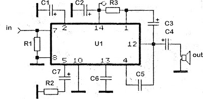
C1 = 47uF
C2 = 100uFC3 = 100uF
C4 = 470uF
C5 = 470pF
C6 = 0.22uF
C7 = 100uF
U1 = KA2203 , SN16975, TBA820, UL1482P
Sunday, October 6, 2013
6 to 12 Volt Converter
Below its a converter circuit voltage from 6 Volt to 12 Volt DC.
 |
| 6 Volt to 12 Volt DC |
Part List :
R1, R4 2 .2K 1/4W Resistor
R2, R3 4.7K 1/4W Resistor
R5 1K 1/4W Resistor
R6 1.5K 1/4W Resistor
R7 33K 1/4W Resistor
R8 10K 1/4W Resistor
C1,C2 0.1uF Ceramic Disc Capacitor
C3 470uF 25V Electrolytic Capcitor
D1 1N914 Diode
D2 1N4004 Diode
D3 12V 400mW Zener Diode
Q1, Q2, Q4 BC547 NPN Transistor
Q3 BD679 NPN Transistor
L1 See Notes
Notes
1. L1 is a custom inductor wound with about 80 turns of 0.5mm magnet wire around a toroidal core with a 40mm outside diameter.
2. Different values of D3 can be used to get different output voltages from about 0.6V to around 30V. Note that at higher voltages the circuit might not perform as well and may not produce as much current. You may also need to use a larger C3 for higher voltages and/or higher currents.
3. You can use a larger value for C3 to provide better filtering.
4. The circuit will require about 2A from the 6V supply to provide the full 800mA at 12V.
Friday, October 4, 2013
Faster Battery Charger Circuit 6 12 Volt with IC LM308 and LM317
This circuit is quickly charging the battery . If you need a faster charger ,this circuit is recomended to you . And this charger is low temperature , the temperatur is 5 degree celcius. Input Voltage is 15 Volt DC , and Output voltage to charging 6 -12V and you can adjust by the D1 (see schematic). And adjust the D1 to 50 mV greater VZ than D2 (see schematic). Couple the D2 to battery. This circuit operating by IC LM308 and LM317 and any other components. And you can use this circuit to charging Accu 6 or 12 Volt , dry or wet and other battery .
See this Schematic Circuit below :

Friday, September 20, 2013
5 Volt Switching Regulator Power Supply
The switching regulator power supply used LM2575-5.0 on this schematic. You can make the stable voltage by using the 3 terminal regulator like LM317. However, because the output electric current and the inputted electric current are the same approximately, the difference between the input electric power (The input voltage x The input electric current) and the output power (The output voltage x The output current) is consumed as the heat with the regulator. Because it is, the efficiency isn�t good.
Data sheet for LM2575
SIMPLE SWITCHER 1A Step-Down Voltage Regulator
http://www.national.com/pf/LM/LM2575.htm
Subscribe to:
Posts (Atom)