Showing posts with label 2. Show all posts
Showing posts with label 2. Show all posts
Wednesday, November 20, 2013
16 × 2 LCD Volt Meter Ampere Meter With PIC
Volt meters & ampere meter with PIC can be used to measure voltage and current simultaneously. The series of volt meters & ampere meter with PIC16F876A PIC is used as a data processor voltage and current are measured.
This circuit uses the viewer in the form of 16 × 2 LCD used for the data display voltage and current measurements. In the article volt meter and ampere meter with PIC are discussed kerannya limited to devices only. More detail can be seen from the image sequence volt meter and ampere meter with PIC below.
The images of Volt Meter & Ampere Meter With PIC Circuit
 |
| Volt meters & ampere meter with PIC |

2 X 30 Watt stereo amplifier by TDA1510
This power amplifier can use IC TDA1510 or TDA1515, minimum voltage require 6 volt and maximum voltage require 18 Volt, Voltage with DC supply voltage.Power output 2x 30 Watt stereo amplifier , with 2 ohms impedance , its is low impedance . You can use the fullrange or woofer speakers. see schematic below :

Tuesday, November 19, 2013
Power Amplifier Circuit 2 x 20 W stereo with IC AN7156N
This circuit operate with IC AN7156N . You just can use this IC , because havnt similarity it. In this Circuit have 2 input IN R and IN L and have Output R and L . Voltage supply require 15 V , minimum voltage 9 V and maximum voltage 24V . And the voltage must DC voltage , and better the DC voltage filtering .
Maximum Output for 1 speaker 25 W , so this circuit have maximum output 2 X 25 W with minimum impedance 4 ohm. See this circuit schematic below :
 |
| Click image to view enlarge |
2 Way Speaker Crossover circuit
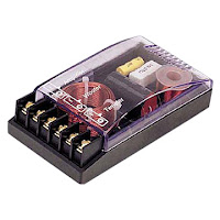
The series of crossover is an electronic circuit in which the point to separate the audio sound frequency. objective that only sound with a frequency range that can be accepted speakers are forwarded. less is more like a filter function, so the speakers work optimally.
2 way or 3 way or else, that determines how many channels would be separated voice. Each channel is handled by a single class of speakers. Eg 3 way, the frequency of sound produced by the head unit, separated by crossover as a low freq (big size distinguished speaker better known as the subwoofer), medium freq (medium speakers), usually in the middle) and hi freq (small speakers I would call a tweeter) Let me better sound and reduce noise.
2 way or 3 way or else, that determines how many channels would be separated voice. Each channel is handled by a single class of speakers. Eg 3 way, the frequency of sound produced by the head unit, separated by crossover as a low freq (big size distinguished speaker better known as the subwoofer), medium freq (medium speakers), usually in the middle) and hi freq (small speakers I would call a tweeter) Let me better sound and reduce noise.
 |
| Schematic 2 Way Speaker Crossover |
Friday, November 1, 2013
IR Remote Control Extender Mark 2
This is an improved IR remote control extender circuit. It has high noise immunity, is resistant to ambient and reflected light and has an increased range from remote control to the extender circuit of about 7 meters. It should work with any domestic apparatus that use 36-38kHz for the IR carrier frequency. Please note that this is NOT compatible with some satellite receivers that use 115KHz as a carrier frequency.

Notes:
The main difference between this version and the previous circuit, is that this design uses a commercially available Infra Red module. This module, part number IR1 is available from Harrison Electronics in the UK. The IR module contains a built in photo diode, amplifier circuit and buffer and decoder. It is centerd on the common 38kHz carrier frequency that most IR controls use. The module removes most of the carrier allowing decoded pulses to pass to the appliance. Domestic TVs and VCRs use extra filtering is used to completely remove the carrier. The IR1 is packaged in a small aluminium case, the connections viewed from underneath are shown below:
Infra Red Module, IR1 Pinout
How It works:
The IR1 module (IC3) operates on 5 Volt dc. This is provided by the 7805 voltage regulator, IC1. Under quiescent (no IR signal) conditions the voltage on the output pin is high, around 5 volts dc. This needs to be inverted and buffered to drive the IR photo emitter LED, LED2. The buffering is provided by one gate (pins 2 & 3) of a hex invertor the CMOS 4049, IC2. The IR1 module can directly drive TTL logic,but a pull-up resistor, R4 is required to interface to CMOS ICs. This resistor ensures that the signal from a remote control will alternate between 0 and 5 volts. As TTL logic levels are slightly different from CMOS, the 3.3k resistor R4 is wired to the +5 volt supply line ensuring that the logic high signal will be 5 volts and not the TTL levels 3.3 volts. The resistor does not affect performance of the IR module, but DOES ensure that the module will correctly drive the CMOS buffer without instability.
The output from the 4049 pin 2 directly drives transistor Q1, the 10k resistor R1 limiting base current. LED1 is a RED LED, it will flicker to indicate when a signal from a remote control is received. Note that in this circuit, the carrier is still present, but at a reduced level, as well as the decoded IR signal. The CMOS 4049 and BC109C transistor will amplify both carrier and signal driving LED2 at a peak current of about 120 mA when a signal is received. If you try to measure this with a digital meter, it will read much less, probably around 30mA as the meter will measure the average DC value, not the peak current. Any equipment designed to work between 36 and 40kHz should work, any controls with carrier frequencies outside this limit will have reduced range, but should work. The exception here is that some satellite receivers have IR controls that use a higher modulated carrier of around 115KHz. At present, these DO NOT work with my circuit, however I am working on a Mark 3 version to re-introduce the carrier.
Parts List:
C1 100u 10V
C2 100n polyester
R1 10k
R2 1k
R3 33R 1W
R4 3k3
Q1 BC109C
IC1 LM7805
IC2 CMOS 4049B
IC3 IR1 module from Harrison Electronics See Last paragraph
LED1 Red LED (or any visible colour)
LED2 TIL38 or part YH70M from Maplin Electronics
Testing:
This circuit should not present too many problems. If it does not work, arm yourself with a multimeter and perform these checks. Check the power supply for 12 Volt dc. Check the regulator output for 5 volt dc. Check the input of the IR module and also Pin 1 of the 4049 IC for 5 volts dc. With no remote control the output at pin 2 should be zero volts. Using a remote control pin 2 will read 5 volts and the Red LED will flicker. Measuring current in series with the 12 volt supply should read about 11mA quiescent, and about 40/50mA with an IR signal. If you still have problems measure the voltage between base and emitter of Q1. With no signal this should be zero volts, and rise to 0.6-0.7 volts dc with an IR signal. Any other problems, please email me, but please do the above tests first.
PCB Template:
Once again a PCB template has been kindly drafted for this project by Domenico.

A magnified view showing the component side is shown below:

Alternatives to IC3:
The part number IR1 from Harrison Electronics is no longer available. They do supply an alternative IR decoder which I have tested and works. Other alternative Infrared decoders are shown below, note however that all DO NOT share the same pinout. I advise anyone making this to check the corresponding data sheets.
Vishay TSOP 1738
Vishay TSOP 1838
Radio Shack 276-0137
Sony SBX 1620-12
Sharp GP1U271R
Equipment Controlled Successfully:
If you have built this circuit and it works successfullt please let me know and I will build the list. Email details of the Manufacturer, device and remote control model number. The remote model number is usually on the front or back of the remote.
Technics CDP770 Remote: EUR64713
Notes:
The main difference between this version and the previous circuit, is that this design uses a commercially available Infra Red module. This module, part number IR1 is available from Harrison Electronics in the UK. The IR module contains a built in photo diode, amplifier circuit and buffer and decoder. It is centerd on the common 38kHz carrier frequency that most IR controls use. The module removes most of the carrier allowing decoded pulses to pass to the appliance. Domestic TVs and VCRs use extra filtering is used to completely remove the carrier. The IR1 is packaged in a small aluminium case, the connections viewed from underneath are shown below:
Infra Red Module, IR1 Pinout
How It works:
The IR1 module (IC3) operates on 5 Volt dc. This is provided by the 7805 voltage regulator, IC1. Under quiescent (no IR signal) conditions the voltage on the output pin is high, around 5 volts dc. This needs to be inverted and buffered to drive the IR photo emitter LED, LED2. The buffering is provided by one gate (pins 2 & 3) of a hex invertor the CMOS 4049, IC2. The IR1 module can directly drive TTL logic,but a pull-up resistor, R4 is required to interface to CMOS ICs. This resistor ensures that the signal from a remote control will alternate between 0 and 5 volts. As TTL logic levels are slightly different from CMOS, the 3.3k resistor R4 is wired to the +5 volt supply line ensuring that the logic high signal will be 5 volts and not the TTL levels 3.3 volts. The resistor does not affect performance of the IR module, but DOES ensure that the module will correctly drive the CMOS buffer without instability.
The output from the 4049 pin 2 directly drives transistor Q1, the 10k resistor R1 limiting base current. LED1 is a RED LED, it will flicker to indicate when a signal from a remote control is received. Note that in this circuit, the carrier is still present, but at a reduced level, as well as the decoded IR signal. The CMOS 4049 and BC109C transistor will amplify both carrier and signal driving LED2 at a peak current of about 120 mA when a signal is received. If you try to measure this with a digital meter, it will read much less, probably around 30mA as the meter will measure the average DC value, not the peak current. Any equipment designed to work between 36 and 40kHz should work, any controls with carrier frequencies outside this limit will have reduced range, but should work. The exception here is that some satellite receivers have IR controls that use a higher modulated carrier of around 115KHz. At present, these DO NOT work with my circuit, however I am working on a Mark 3 version to re-introduce the carrier.
Parts List:
C1 100u 10V
C2 100n polyester
R1 10k
R2 1k
R3 33R 1W
R4 3k3
Q1 BC109C
IC1 LM7805
IC2 CMOS 4049B
IC3 IR1 module from Harrison Electronics See Last paragraph
LED1 Red LED (or any visible colour)
LED2 TIL38 or part YH70M from Maplin Electronics
Testing:
This circuit should not present too many problems. If it does not work, arm yourself with a multimeter and perform these checks. Check the power supply for 12 Volt dc. Check the regulator output for 5 volt dc. Check the input of the IR module and also Pin 1 of the 4049 IC for 5 volts dc. With no remote control the output at pin 2 should be zero volts. Using a remote control pin 2 will read 5 volts and the Red LED will flicker. Measuring current in series with the 12 volt supply should read about 11mA quiescent, and about 40/50mA with an IR signal. If you still have problems measure the voltage between base and emitter of Q1. With no signal this should be zero volts, and rise to 0.6-0.7 volts dc with an IR signal. Any other problems, please email me, but please do the above tests first.
PCB Template:
Once again a PCB template has been kindly drafted for this project by Domenico.
The part number IR1 from Harrison Electronics is no longer available. They do supply an alternative IR decoder which I have tested and works. Other alternative Infrared decoders are shown below, note however that all DO NOT share the same pinout. I advise anyone making this to check the corresponding data sheets.
Vishay TSOP 1738
Vishay TSOP 1838
Radio Shack 276-0137
Sony SBX 1620-12
Sharp GP1U271R
Equipment Controlled Successfully:
If you have built this circuit and it works successfullt please let me know and I will build the list. Email details of the Manufacturer, device and remote control model number. The remote model number is usually on the front or back of the remote.
Technics CDP770 Remote: EUR64713
Sunday, October 27, 2013
2 X 0 6W schematic audio amplifier
This schematic have require minimum voltage at 1Volt and maximum volotage at 9 Volt. Maximum output power 2 X 0.6W.

Part List:
Capacitor
C1 = 100uF
C2 = 220uF
C3 = 220uF
C4 = 220uF
C5 = 220uF
IC = ULN3782
Wednesday, October 16, 2013
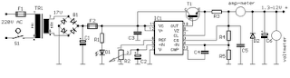
1 3 12 2 VDC Variable Power Supply
Power supply circuit to generate output below were variations between 1.3V DC to 12.2V DC with 1A current.
Next full text...
In addition, the power supply circuit is also equipped with over-current protection or shield against belebih flow. Power supply circuit is very simple, but the quality is quite good, made her basiccally regulator IC LM723 is a fairly legendary.
Friday, October 11, 2013
2 X 30Watt home amplifier circuit
Audio amplifier circuit is very suitable for use at home, using a subwoofer speaker, or woofer speaker. Usually, also called home amplifier, audio amplifiers are based on the IC and ic are used still in series with type STK457 STK and besides it also can use the STK459, 460, 461, 463, 465. And each ic has the quality of each one, please look at alldatasheet.com.
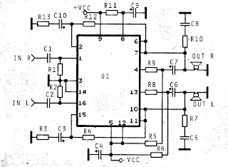
C5 = 0.1uF
C8 = 0.1uF
Next full text...
Part List :
R1 = 22K
R2 = 22K
R3 = 330R
R4 = 33K
R5 = 1K
R6 = 1K
R7 = 4.7R
R8 = 3K3
R9 = 3K3
R10 = 4.7R
R11 = 100R
R12 = 33KR13 = 330R
C1 = 0.1uF
C2 = 0.1uF
C3 = 100uF
C4 = 100uFC5 = 0.1uF
C6 = 47uF
C7 = 47uFC8 = 0.1uF
C9 = 100uF
C10 = 100uFU1 = STK457,STK459, 460, 461, 463, 465.
Thursday, October 10, 2013
2 X 30Watt home amplifier circuit
Audio amplifier circuit is very suitable for use at home, using a subwoofer speaker, or woofer speaker. Usually, also called home amplifier, audio amplifiers are based on the IC and ic are used still in series with type STK457 STK and besides it also can use the STK459, 460, 461, 463, 465. And each ic has the quality of each one, please look at alldatasheet.com.
C5 = 0.1uF
C8 = 0.1uF
Next full text...
Part List :
R1 = 22K
R2 = 22K
R3 = 330R
R4 = 33K
R5 = 1K
R6 = 1K
R7 = 4.7R
R8 = 3K3
R9 = 3K3
R10 = 4.7R
R11 = 100R
R12 = 33KR13 = 330R
C1 = 0.1uF
C2 = 0.1uF
C3 = 100uF
C4 = 100uFC5 = 0.1uF
C6 = 47uF
C7 = 47uFC8 = 0.1uF
C9 = 100uF
C10 = 100uFU1 = STK457,STK459, 460, 461, 463, 465.
Saturday, September 28, 2013
2 X 0 6W schematic audio amplifier
This schematic have require minimum voltage at 1Volt and maximum volotage at 9 Volt. Maximum output power 2 X 0.6W.
Part List:
Capacitor
C1 = 100uF
C2 = 220uF
C3 = 220uF
C4 = 220uF
C5 = 220uF
IC = ULN3782
Saturday, September 21, 2013
2 5 Watt audio amplifier circuit diagram
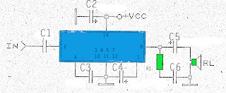
The above is a simple amplifier circuit also has a minimal power output. By using only a few components and a single IC as the basis for the strengthening of the amplifier, this circuit has a power output of not more than 2.5 W and impedance or RL 8. Requires a minimum voltage of this amplifier is around 6V and 26V maximum voltage, the voltage must be DC or already rectified and filtered.Part List :
R1 = 1R
C1 = 0.1uF
C2 = 100uF
C3 = 0.1uF
C4 = 5uF
C5 = 500uF
C6 = 0.1uF
IC = ULN2280B , ULN2281B , ULN3784B.
Friday, September 20, 2013
Car Amplifier Circuit 2 x 30 W stereo
This circuit use the IC AN7166 . On circuit have an advantage is very loud sound , although only 30W this circuit is like a 100 W transistor power amplifier. Its so good circuit with IC AN7166 . This circuit require minimum voltage 12 V and Maximum voltage 24 volt , I recomended voltage for this circuit is 18 volt. And use the battery supply current 5 Ampere. Maximum power output of one speaker 30 W with impedance 4 Ohm.
See this circuit schematic below :
 |
| Click image to view large |
Capacitor thats connect legs IC 4 and 3 is 1 nF . And capacitor thats connect legs IC 9 and 3 is 1 nF. For the input capacitor at 1 uF ( L and R ) for output capacitor at 1000uF with voltage 50 V or higher.
Subscribe to:
Posts (Atom)