Showing posts with label watt. Show all posts
Showing posts with label watt. Show all posts
Tuesday, January 21, 2014
1200 Watt Subwoofer Energy ESW M8 NA

 One of the most important speakers in any system, the subwoofer is often relegated to a back corner and nearly forgotten. At Energy, however, we invest a great deal of design time and effort into building the industry’s best subwoofers, offering unparalleled performance and flexibility. The ESW-M8 is no exception. The ESW-M8 subwoofer delivers deep, accurate effects with 1200 peak watts of room-filling power—all from a 9-inch cube.
The ESW-M8 features an 8-inch anodized aluminum cone woofer with Ribbed Elliptical Surround for tight and powerful bass response and two 8-inch anodized aluminum cone passive radiators that eliminate port noise that allows for deep bass extension. With a variable low pass filter of 50Hz-200Hz, you get versatile blending using the built-in crossover or your surround processor. The furniture grade high gloss black cabinet provides versatility and will blend into your décor. It’s the ideal companion to any front, center, and surround channels, whether you’re looking to achieve a 5.1 system or a 5.1 on the Richter scale.
Ribbed Elliptical Surround
This tiny beast features our patented Ribbed Elliptical Surrounds, which mates perfectly with a powerful amplifier to provide your audio experience with plenty of pure bass. The Ribbed Elliptical Surrounds that encircle Energys products woofers are unlike any other. By changing the shape of the speaker surround to an ellipse, rather than the traditional "half roll," distortion is reduced dramatically. Side benefits include increased excursion and larger piston area, allowing for greater efficiency. Energys cast basket woofers also feature this technology, allowing the surround to stretch and contract as it moves, eliminating dimpling.
Selectable Auto Power Switch
The featured power switch can be set to either On, Off or Auto. If the switch is in the Off position, the subwoofer will not power up. If the switch is in the On position, it will constantly remain on. If the switch is set to the Auto position, when a signal is present the subwoofer will turn on and will automatically turn off several minutes after a signal is no longer present.
Low-Pass Filter and Phase Controls
The low-pass filter control allows for the adjustment of the low-pass filter. Adjustments can infinitely be made from 50Hz to 200Hz. This will determine the highest frequency that the subwoofer will reproduce for a custom sound fitted to your room. Setting the crossover too low will create a gap between the frequency response of the front speakers and that of the subwoofer, while setting the crossover frequency too high will create a doubling of certain frequencies, making the music sound boomy.
The phase control switch allows for the adjustment of the phase of the subwoofer, in relation to the speakers used in your system, from 0 to 180 degrees, to give your home theater system the right balance. This control ensures that the subwoofer operates in phase with the rest of the system, as an out of phase subwoofer will either sound like it is lacking in bass performance or that its timing is off. This setting will be determined by your listening position, the characteristics of your listening room and its interaction with your Energy subwoofer.
About Energy
Energy, admittedly, is a bold name for a speaker. Fortunately for you, you’re looking at some highly dynamic audio generators. We’re talking crystal clear dialogue. Big booms, bangs, and ka-thuds from your favorite flicks. And music that’ll rock your soul. That’s what you get when teams of dedicated engineers work alongside expert designers. For more than 30 years, they’ve been researching the scientific principles of sound and using the most modern materials available. They’ve fine-tuned each speaker according to the three major aspects of loudspeaker performance: wide dispersion, low distortion, and flat frequency response. And they’ve customized and re-customized every little component, resulting in one-of-a-kind modifications like our patented Ribbed Elliptical Surrounds, for better bass, and the Convergent Source Module (CSM), for accurate sound. And, while all that audio research is great, in the end all that matters is that when you crank the volume, what you’ll hear is sound perfected. What you’ll feel is pure Energy.

Monday, December 16, 2013
Simple 100 Watt Inverter
This is a simplest circuit for 100 watt inverter for generating 220vAC from 12vDC. I say simplest because here in this inverter circuit a minimum number of components are used to design the schematic, which is quite difficult to make a circuit like this with further fewer components.
Simple 100 Watt Inverter Circuit Diagram

This 100W inverter circuit works great for small loads like a fan or 2-3 bulbs/lamps. In this circuit as IC1 we used a CD 4047 IC to generate 100Hz frequency (180 degree out of phase). CD 4047 IC is from Texas Instruments. It is mostly used as Astable/Monostable signal generator device. In this circuit it is triggered as astable multivibrator by the capacitor C1 between the Pin 1 and 3 of CD4047. And VR1 is used to adjust the frequency of signal.
Four 2N3055 transistors are used to amplify the pulse trains that are pre-amplified by two TIP122 transistors. There used three transistors for each side (half cycle), one TIP122 & two 2N3055 transistor to drive the output transformer (TX in circuit). Four 2N3055 transistors are used as driving transistor. An inverters maximum output power depends on two factors; one is the max current rating of transformer’s primary winding and other factor is the current rating of driver transistors.
Transformer: Use a 12v-0-12v, 10A step-down transformer in reverse. That’s mean secondary winding (12v-0-12v) will be the primary and primary winding (220VAC side) will be the secondary (output). So that it will worked like a step-up transformer. You can also use a 5A transformer instead of 10A, if you couldn’t have 10A. But the output power will decrease to 60 Watt.
+12VDC: A good quality 12V car battery could be used for DC 12V.
Parts list :
VR1 = 250K (Variable resistor/POT)
R1, R2 = 4.7K-1/4W Resistor
R3, R4, R5, R6 = 0.1R-5W
C1 = 0.022uF
C2 = 220uF-25V
D1 = BY127 Diode
D2 = 9.1V Zener Diode
Q1, Q4 = TIP122 Transistor
Q2, Q3, Q5, Q6 = 2N3055 Transistor
F1 = 10A Fuse
IC1 = CD4047
TX = 12-0-12V, 10A Step-down Transformer
VR1 = 250K (Variable resistor/POT)
R1, R2 = 4.7K-1/4W Resistor
R3, R4, R5, R6 = 0.1R-5W
C1 = 0.022uF
C2 = 220uF-25V
D1 = BY127 Diode
D2 = 9.1V Zener Diode
Q1, Q4 = TIP122 Transistor
Q2, Q3, Q5, Q6 = 2N3055 Transistor
F1 = 10A Fuse
IC1 = CD4047
TX = 12-0-12V, 10A Step-down Transformer
Wednesday, November 20, 2013
2 X 30 Watt stereo amplifier by TDA1510
This power amplifier can use IC TDA1510 or TDA1515, minimum voltage require 6 volt and maximum voltage require 18 Volt, Voltage with DC supply voltage.Power output 2x 30 Watt stereo amplifier , with 2 ohms impedance , its is low impedance . You can use the fullrange or woofer speakers. see schematic below :

140W Amplifier Circuit 2x 70 Watt
Stereo Power Amplifier is 2x70Watt STA550 chip audio power with BASH concept that can be connected with digital perangkkat. 2x70Watt STA550 Stereo Power Amplifier is an amplifier with BTL system with symmetrical power supply with ground. Power amplifier STA550 uses power output transistor which is on the chip and is set to produce a high efficiency audio power.
Power output on the STA550 is using the system without copling ac bridge (direct) and zero offset. Strengthening of the STA550 from stereo power amplifier is +12 dB. 2x70Watt STA550 Stereo Power Amplifier is equipped with temperature sensors for protection from overheating and current-limiting protection system for power amplifier. 2x70Watt STA550 Stereo Power Amplifier is equipped with standby and mute controls to regulate silent or active mode power amplifier.
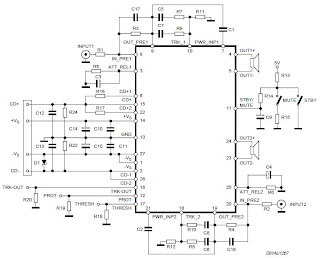
Feature Stereo Power Amplifier 2x70Watt STA550 :
Monochip Bridge Stereo Amplifier dengan Bash® Architecture55+55w Output Power @ Rl = 4/8 W, Thd = 0.5%
70+70w Output Power @ Rl = 4/8 W, Thd = 10%
High Dynamic Preamplifier Input Stages
External Programmable Feedback Type Compressors
Ac Coupled Input To Class Ab Bridge Output Amplifier
Precision Rectifiers To Drive The Digital Converter
Proportional Over Power Output Current To Limit The Digital Converter
Absolute Power Bridge Output Transistor Power Protection
Absolute Output Current Limit
Integrated Thermal Protection
Power Supply Over Voltage Protection Flexiwatt Power Package With 27 Pin
Bash® Licence Required
Tuesday, October 29, 2013
14 Watt car audio amplifier circuit

Basic operation of this amplifier is on IC TEA2021 ,
In this circuit minimum require voltage is 4 volts and maximum voltage 25 volts. Power output 14 Watt with 4 Ohm impedance. See this schematic.
Saturday, October 26, 2013
6 Watt stereo power amplifier schematic
Basiccally,this amplifier works with the IC, which is where ic is associated with several other components in the supply and use DC voltage, which corresponds to the needs of IC above course on the circuit schematic. For IC , stands intregated circuit used is ic LM379 which has a maximum 6 Watt stereo output. This IC manufactered by NS and with SDIP-14 package. While other components needed in the circuit schematic , you can see components of the list below.

Resistor
R1___________________2K
R2___________________2K
R3___________________33K
R4___________________33K
R5___________________1M
R6___________________1M
R7___________________10R 2W
R8___________________10R 2W
Capacitor
C1___________________4.7uF
C2___________________4.7uF
C3___________________470uF
C4___________________470uF
C5___________________470uF
C6___________________100n
C7___________________100n
IC
IC1___________________LM379
Wednesday, October 23, 2013
60 Watt Subwoofer Amplifer Circuit
THis is very nice amplifier circuit , because High output , and voltage required is also not too large, and suitable for th subwoofer speaker.This circuit use IC TDA1102 , Minimum require voltage 6 volt and maximum voltage 16 volt with impedance 4 ohm . This circuit perfect those of you wear the speakers subwoofer especially in the small room , like in the car. See circuit subwoofer below :

Next full text...
Friday, October 18, 2013
5 8 Watt audio power amplifier
This amplifier circuit has a power output of a small or too low at 5.8 Watt, which uses IC KA2205. The required voltage for at least 6 volts to 18 volts DC maximum.
Schematics power audio amplifier with IC KA2205
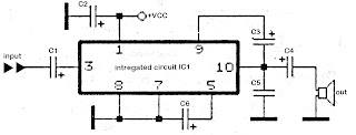
Component List
C1 = 1uF
C2 = 100uFC3 = 47uF
C4 = 1000uFC5 = 0.1uF
C6 = 220uF
IC1 = KA2205
Monday, October 14, 2013
90 Watt Switching Power Supply
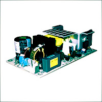
Switching Power Supply in this article are able to supply power 90 Watt. Switching Power Supply series is built directly from an AC network system using special IC MC33374 switching power supply in the form of High Voltage Power Switching Regulator and with external components to the other.
IC MC33374 IC is a switching power supply designed to operate with an AC voltage source and works as a power switching converter with flyback technique. Switching Power Supply Series has a 15 volt DC output with current up to 6 Ampere.
IC MC33374 IC is a switching power supply designed to operate with an AC voltage source and works as a power switching converter with flyback technique. Switching Power Supply Series has a 15 volt DC output with current up to 6 Ampere.
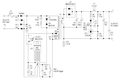 |
| 90 Watt Switching Power Supply Schematic |
Series 90 Watt Switching Power Supply works by menyearahkan AC source is then used to activate the converter MC33374 system. The output of transformer switching converter MC33374 searahkan again later on as a DC voltage supply to be used for electronic devices.
Wednesday, October 2, 2013
60 watt power amplifier circuit with TDA1512
This is low noise power amplifier , high output power amplifier for full range speakers, but you can use the woofer speakers to this circuit . Maximum output power 60 Watt with impedance 4 Ohms see circuit below :

Minimum Supply Voltage : 12-Volt DC
Maximum Supply Voltage : 25-Volt DC
Maximum Power Output : 60 Watts
Impedance Speaker : 4 Ohm
Current Voltage : 3A
Sunday, September 29, 2013
3 Watt stereo amplifier circuit
3 Watt stereo amplifier circuit using MAX 7910 IC. The MAX9710 a stereo audio power amplifier IC capable of delivering 3Watts of out put to 4 Ohm loads. MAX9710 can be operated from a single 4.5V to 5.5V power supply , makes it ideal for hand held applications.The IC for 3 Watt stereo amplifier circuit also features thermal overload protection.
Circuit Schematics 3 Watt Stereo Amplifier MAX 7910
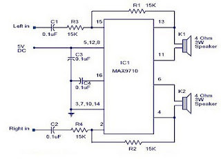 |
| 3 Watt stereo amplifier circuit |
This 3 Watt stereo amplifier circuit is suitable for small power audio devices such as radio sets and portable CD players. 5 V DC power supply is used for powering the 3 Watt stereo amplifier circuit. 6V battery with an IN 4007 diode series to the positive terminal of it can also be used instead of 5 V DC supply. The 3 Watt stereo amplifier circuit will get a supply voltage approximately 5 V after 0.7 V voltage drop across diode.
Saturday, September 21, 2013
2 5 Watt audio amplifier circuit diagram
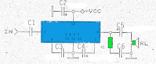
The above is a simple amplifier circuit also has a minimal power output. By using only a few components and a single IC as the basis for the strengthening of the amplifier, this circuit has a power output of not more than 2.5 W and impedance or RL 8. Requires a minimum voltage of this amplifier is around 6V and 26V maximum voltage, the voltage must be DC or already rectified and filtered.Part List :
R1 = 1R
C1 = 0.1uF
C2 = 100uF
C3 = 0.1uF
C4 = 5uF
C5 = 500uF
C6 = 0.1uF
IC = ULN2280B , ULN2281B , ULN3784B.
Saturday, September 14, 2013
60 Watt 2N3055 Power Amplifier
Simple and low cost. The optimal accumulation voltage is about 50V, but this amp assignment from 30 to 60V. The acute ascribe voltage is about 0.8 – 1V.
As you can see, in this architecture the apparatus accept a big tolerance, so you can body it about of the components, which you acquisition at home. The and transistors can be any NPN blazon ability transistor, but do not use Darlington types… The achievement ability is about 60W.
As you can see, in this architecture the apparatus accept a big tolerance, so you can body it about of the components, which you acquisition at home. The and transistors can be any NPN blazon ability transistor, but do not use Darlington types… The achievement ability is about 60W.
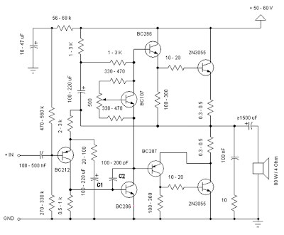 |
| Click to view larger 2N3055 Power Amplifier Circuit Schematic Figure |
- capacitor C1 regulates the low frequencies (bass), as the capacitance grows, the low frequncies are accepting louder.
- capacitor C2 regulates the college frequencies (treble), as the capacitance grows, the college frequencies are accepting quiter.
- this is a chic B amplifier, this means, that a accepted charge breeze through the end transistors, alike if there is no arresting on the input. This accepted can be adapted with the 500Ω trimmer resistor. As this accepted incrases, the complete of the amplifier gets better, but the end transistors are added heating. But if this accepted decrases, the transistors are not heating so much, but the complete gets worse…
Friday, September 13, 2013
0 5 Watt power amplifier circuit with TDA1015T
This circuit is also Very simple and easy to make , simply by using the IC and 6 other components such as resistor and capacitor, you have to run this circuit. The IC uses TDA1015T , minimum voltage require 3 volt and maximum voltage required 12 volt. Power output 0,5 Watt mono , its low power amplifier.
Power amplifier Schematic below :
 |
| Click image to view larger |
If the amplifier does not work , please check :
- Supply voltage
- Components , its damaged or not.
- Input connected or not
- Output connected or not
- Supply voltage of each components
- Line PCB.
Subscribe to:
Posts (Atom)