Showing posts with label subwoofer. Show all posts
Showing posts with label subwoofer. Show all posts
Tuesday, January 21, 2014
1200 Watt Subwoofer Energy ESW M8 NA

 One of the most important speakers in any system, the subwoofer is often relegated to a back corner and nearly forgotten. At Energy, however, we invest a great deal of design time and effort into building the industry’s best subwoofers, offering unparalleled performance and flexibility. The ESW-M8 is no exception. The ESW-M8 subwoofer delivers deep, accurate effects with 1200 peak watts of room-filling power—all from a 9-inch cube.
The ESW-M8 features an 8-inch anodized aluminum cone woofer with Ribbed Elliptical Surround for tight and powerful bass response and two 8-inch anodized aluminum cone passive radiators that eliminate port noise that allows for deep bass extension. With a variable low pass filter of 50Hz-200Hz, you get versatile blending using the built-in crossover or your surround processor. The furniture grade high gloss black cabinet provides versatility and will blend into your décor. It’s the ideal companion to any front, center, and surround channels, whether you’re looking to achieve a 5.1 system or a 5.1 on the Richter scale.
Ribbed Elliptical Surround
This tiny beast features our patented Ribbed Elliptical Surrounds, which mates perfectly with a powerful amplifier to provide your audio experience with plenty of pure bass. The Ribbed Elliptical Surrounds that encircle Energys products woofers are unlike any other. By changing the shape of the speaker surround to an ellipse, rather than the traditional "half roll," distortion is reduced dramatically. Side benefits include increased excursion and larger piston area, allowing for greater efficiency. Energys cast basket woofers also feature this technology, allowing the surround to stretch and contract as it moves, eliminating dimpling.
Selectable Auto Power Switch
The featured power switch can be set to either On, Off or Auto. If the switch is in the Off position, the subwoofer will not power up. If the switch is in the On position, it will constantly remain on. If the switch is set to the Auto position, when a signal is present the subwoofer will turn on and will automatically turn off several minutes after a signal is no longer present.
Low-Pass Filter and Phase Controls
The low-pass filter control allows for the adjustment of the low-pass filter. Adjustments can infinitely be made from 50Hz to 200Hz. This will determine the highest frequency that the subwoofer will reproduce for a custom sound fitted to your room. Setting the crossover too low will create a gap between the frequency response of the front speakers and that of the subwoofer, while setting the crossover frequency too high will create a doubling of certain frequencies, making the music sound boomy.
The phase control switch allows for the adjustment of the phase of the subwoofer, in relation to the speakers used in your system, from 0 to 180 degrees, to give your home theater system the right balance. This control ensures that the subwoofer operates in phase with the rest of the system, as an out of phase subwoofer will either sound like it is lacking in bass performance or that its timing is off. This setting will be determined by your listening position, the characteristics of your listening room and its interaction with your Energy subwoofer.
About Energy
Energy, admittedly, is a bold name for a speaker. Fortunately for you, you’re looking at some highly dynamic audio generators. We’re talking crystal clear dialogue. Big booms, bangs, and ka-thuds from your favorite flicks. And music that’ll rock your soul. That’s what you get when teams of dedicated engineers work alongside expert designers. For more than 30 years, they’ve been researching the scientific principles of sound and using the most modern materials available. They’ve fine-tuned each speaker according to the three major aspects of loudspeaker performance: wide dispersion, low distortion, and flat frequency response. And they’ve customized and re-customized every little component, resulting in one-of-a-kind modifications like our patented Ribbed Elliptical Surrounds, for better bass, and the Convergent Source Module (CSM), for accurate sound. And, while all that audio research is great, in the end all that matters is that when you crank the volume, what you’ll hear is sound perfected. What you’ll feel is pure Energy.

Thursday, November 7, 2013
Gambar Skema Rangkaian Subwoofer Filter Mobil
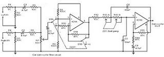 Gambar Skema Rangkaian Subwoofer Filter Mobil
The circuit is designed around the TL072 dual BIFET opamp IC. Out of the two opamps inside the chip, IC1A is wired as a buffer. The left & right audio inputs after mixing is fed to the input of the IC1A using the DPDT switch S1. Switch S1 is the phase control switch which can be used to make the subwoofer in phase with other speakers. When S1 is in position 2, 180 degree phase shift will be induced.POT R7 can be used for controlling the level. IC1B forms the low pass filter whose pass frequency can be controlled by adjusting the dual gang POT R13.
Here is the circuit diagram of a simple subwoofer filter that can be operated from a 12V DC supply. Such a circuit is useful in automobile subwoofer applications. The circuit is nothing but a low pass filter whose pass frequency can be adjusted between 60 to 160 Hz.
Here is the circuit diagram of a simple subwoofer filter that can be operated from a 12V DC supply. Such a circuit is useful in automobile subwoofer applications. The circuit is nothing but a low pass filter whose pass frequency can be adjusted between 60 to 160 Hz.
Saturday, October 26, 2013
Filter PreAmp Subwoofer
Acoustic spectrum is extended by the 20Hz frequency is very low and reaches as high frequency 20000Hz. In the low frequency is lowered sense of direction. This reasoning leads us to attribute to the speakers use of very low frequency. Making it to you we propose to distinguish these frequencies, in order for him to lead us on a suitable amplifier.
Acoustic filter are met at different points in the sound system. Applications knownest they are filter baxandal to organize low-and high-frequency tones and crossover filter where the acoustics are separated in the subareas, for it leads to the appropriate speakers. Applications that you can we propose is a simple filter that limits the acoustic region (20-20000Hz) in 20-100Hz region.
Acoustic filter are met at different points in the sound system. Applications knownest they are filter baxandal to organize low-and high-frequency tones and crossover filter where the acoustics are separated in the subareas, for it leads to the appropriate speakers. Applications that you can we propose is a simple filter that limits the acoustic region (20-20000Hz) in 20-100Hz region.
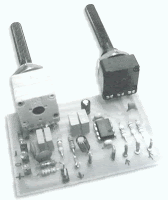
With manufacturing, we propose that you can you can make an active filter for you lead a very low frequency loudspeaker. With this you will put a big one between speaker HIFI speakers from you. In order for you to have a complete picture of sound you will need also an appropriate amplifier. In the entry of circuit you will connect the two roads out of the preamplifier or the exit of the preamplifier few. The series production in order to allocate out of the facility led a series of subwoofer power. If for some reason you do not have space for you to put the third speaker in the courtroom, then you can choose a smaller speaker. This output will depend on the type of music that you hear. If in deed you have the space, then after you create a filter and still say thank you, you can he recommend your friends or still makes each other to your friends.
Circuit diagram
 |
| Filter | PreAmp Subwoofer circuit diagram |
Parts
R1 = 39 Kohm
R2 = 39 Kohm
R3 = 47 Kohm
R4 = 10 Ohm
R5 = 22 Kohm
R6 = 4.7 Kohm
R7 = 22 Kohm
R8 = 4.7 Kohm
R9 = 10 Ohm
R10 = 220 Ohm
C1 = 39 pF
C2 = 0.1 UF
C3 = 0.1 UF
C4 = 0.2 UF
C5 = 0.4 UF
C6 = 0.1 UF
C7 = 0.1 UF
IC1 = TL064
In the form that appears theoretical filter circuit. At first glance we see three different circuits which are mainly produced by two rounds of operational amplifiers. This circuit is a mixture, with the assistance variable amplifier and variable filters. Late-making requires a series of operations catering catering with the same trend with  ± 12. operational amplifier which is the active element for this circuit is the type of dual operation as a TL082 and NE5532. The operational amplifier is included in a family is equipped with field-effect transistor IFET in their entries. Each member is allocated a family in bipolar transistor circuits and field effect. This circuit can function in a high inclination, because of their high propensity to use transistors. Also they have the high honor rhythm elevation (slew rate), low polarization at this time for entry and little influenced by temperature. The operational amplifier has an area of 3MHz unity gain bandwidth. Another important element for them is a great choice reject noise, there are currently in the line of catering.
Price refused to greater than 80dB, their consumption is small, from 11 to 3 mA. They briefly sold internally with eight pins and allocate two operational amplifiers, In the same row 14 pin in short they combine four operations, the trade them for sale with code TL074, TL084 and TL064, a nutshell with eight pins they sold the operational amplifier TL071 TL061 kajTL081 . In manufacturing we use the TL082 that has two operational. First operation of TL082 he worked as an amplifier and mixed with two channels, the entry is negative, it is a little mixed with the two resistances. A potentiometer on the steps of determining the aid circuit. At this point the left wing and right-channel preamplifier they added means of two resistances. En operational continuity with the help strengthen the signal is made depending on the price that has been potentiometer.
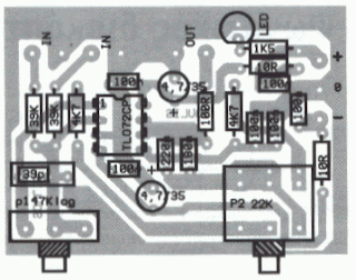 |
| PCB layout |
Place runner comparable with the assistance of the circuit. The second operational amplifier is a filter manufacturing. Filters from the acoustic frequency from second grade and he made a round of operational amplifiers. This filter section with variable frequency low-cut. This frequency can be changed and took the price of very low frequency of 30Hz or still exceeds 150Hz. The frequency of the filter depends on the price cuts that have circuit elements. Change the value of the elements that we can have a frequency cut 150Iz, 130Hz, 100Hz, 7A? Z, 6A? Z even 3A? Z, is the price that they can be achieved by simple rotation of the double potentiometer. Filter circuit has been made about an operation that has completed a TL082 dual operational amplifier. In the filter out we will connect the plug load which is connected amplifier. In a series of exit are presented, which are limited as to the extent of frequency, the signal applied in the entry of the circuit.
Thursday, October 24, 2013
600W subwoofer audio amplifier with 20 channel mixer and parametric
This picture below is about my setup subwoofer amplifier with 20 CH mixer and parametric. This amplifier use transformer 10 ampere to supply the power and 3 ampere transformer use to supply mixer and parametric.Elco capacitor that i use for the transformer 10 A, only 10000uF numbered 2. The circuit of amplifiers that i use which is 600 watt mono subwoofer amplifier . And booster amplifier only use 2 Sanken transistors. See picture subwoofer amplifier assemblies below :
 |
| Looked over the side |
 |
| Front view |
 |
| Back top |


Wednesday, October 23, 2013
60 Watt Subwoofer Amplifer Circuit
THis is very nice amplifier circuit , because High output , and voltage required is also not too large, and suitable for th subwoofer speaker.This circuit use IC TDA1102 , Minimum require voltage 6 volt and maximum voltage 16 volt with impedance 4 ohm . This circuit perfect those of you wear the speakers subwoofer especially in the small room , like in the car. See circuit subwoofer below :

Next full text...
Sunday, October 20, 2013
300W subwoofer amplifier schematic
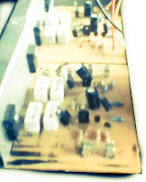 This is an amplifier circuit that is formed from a transistor amplifier miraculous. This circuit is used in the speaker subwoofer with 300W maximum power on each side. To apply it, can be used in the room that is not too large, like the car. And the voltage needed between 25 to 42 Volt DC.
This is schematic of 300W subwoofer amplifier

Friday, October 18, 2013
Subwoofer Amplifier with STK4241V
The Subwoofer Amplifier based STK4241V was posted by in the sphere of kind Amplifier. Please examine suspiciously and look by the side of schematic design photos of Subwoofer Amplifier based STK4241V to achieve note in a row.
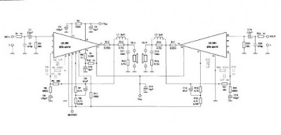
This Subwoofer Amplifier is equiped with STK4241V wich is a clot avenue intercrossed IC, AF Cognition Amplifier (Separate Superpower action) (120W+120W min, THD = 0.08%). STK4241V has not many skin tone analogous: Muting circuit built-participating in to padding all types of puzzlement disturbance, spanking mirror track on behalf of low 0.08% corps sweet form. For this 2×120W state stereo alphabetical listing oftenness amplifier we draw on a sole monochip STK4241V to attain up to 120W for both transmission.
Sunday, October 13, 2013
Subwoofer Filter with LM741
The acoustics of converting a filter, near are many aspects of the financially viable possibility of the further famous are Baxandal filter low and soaring frequency filters and crossover Acoustic area is transformed into subordinate-domains, so with the purpose of the Thursday Speakers. Applications, we offer a filter, the limits of the region to transform acoustic (20-20000Hz) happening the region of 20-100Hz.
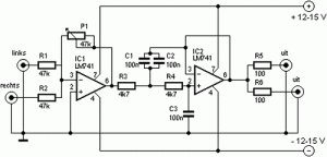
The make signs on behalf of a head high pass filter C1, C2, P1, which is undesirable level DC input. A lowpass filter consisting of R3, R4, C3 prevents frequencies on top of 10 kHz, which look after not benefit from this design, and it would come about so as to the instability and clatter. The precipitate amp invert make signs.
The low Summary of the amplifier signals extend to a next low-pass filter to prevent the frequency from the speakers.
I unambiguous, a second order, because this box with a bunged place bring out. If you give birth to a circuit with a valve coordination, and therefore simply close the Wind (Roll a pair off of socks and pick by the docks / Wind), this preference bequeath you a sealed box as a replacement for.
Saturday, October 12, 2013
Subwoofer Pre Amp Filter
Acoustic spectrum is extended by the 20Hz frequency is very low and reaches as high frequency 20000Hz. In the low frequency is lowered sense of direction. This reasoning leads us to attribute to the speakers use of very low frequency. Making it to you we propose to distinguish these frequencies, in order for him to lead us on a suitable amplifier.
Acoustic filter are met at different points in the sound system. Applications knownest they are filter baxandal to organize low-and high-frequency tones and crossover filter where the acoustics are separated in the subareas, for it leads to the appropriate speakers. Applications that you can we propose is a simple filter that limits the acoustic region (20-20000Hz) in 20-100Hz region.
With manufacturing, we propose that you can you can make an active filter for you lead a very low frequency loudspeaker. With this you will put a big one between speaker HIFI speakers from you. In order for you to have a complete picture of sound you will need also an appropriate amplifier. In the entry of circuit you will connect the two roads out of the preamplifier or the exit of the preamplifier few.
The series production in order to allocate out of the facility led a series of subwoofer power. If for some reason you do not have space for you to put the third speaker in the courtroom, then you can choose a smaller speaker. This output will depend on the type of music that you hear. If in deed you have the space, then after you create a filter and still say thank you, you can he recommend your friends or still makes each other to your friends.
Circuit diagram |
| Filter | PreAmp Subwoofer circuit diagram |
Parts
R1 = 39 Kohm , R2 = 39 Kohm,R3 = 47 Kohm,R4 = 10 Ohm,R5 = 22 Kohm,R6 = 4.7 Kohm,R7 = 22 Kohm, R8 = 4.7 Kohm, R9 = 10 Ohm, R10 = 220 Ohm, C1 = 39 pF,C2 = 0.1 UF,C3 = 0.1 UF, C4 = 0.2 UF, C5 = 0.4 UF, C6 = 0.1, UF C7 = 0.1 UF, IC1 = TL064
In the form that appears theoretical filter circuit. At first glance we see three different circuits which are mainly produced by two rounds of operational amplifiers. This circuit is a mixture, with the assistance variable amplifier and variable filters. Late-making requires a series of operations catering catering with the same trend with  ± 12. operational amplifier which is the active element for this circuit is the type of dual operation as a TL082 and NE5532.
The operational amplifier is included in a family is equipped with field-effect transistor IFET in their entries. Each member is allocated a family in bipolar transistor circuits and field effect. This circuit can function in a high inclination, because of their high propensity to use transistors. Also they have the high honor rhythm elevation (slew rate), low polarization at this time for entry and little influenced by temperature. The operational amplifier has an area of 3MHz unity gain bandwidth. Another important element for them is a great choice reject noise, there are currently in the line of catering.
Price refused to greater than 80dB, their consumption is small, from 11 to 3 mA. They briefly sold internally with eight pins and allocate two operational amplifiers, In the same row 14 pin in short they combine four operations, the trade them for sale with code TL074, TL084 and TL064, a nutshell with eight pins they sold the operational amplifier TL071 TL061 kajTL081 . In manufacturing we use the TL082 that has two operational. First operation of TL082 he worked as an amplifier and mixed with two channels, the entry is negative, it is a little mixed with the two resistances. A potentiometer on the steps of determining the aid circuit. At this point the left wing and right-channel preamplifier they added means of two resistances. En operational continuity with the help strengthen the signal is made depending on the price that has been potentiometer.
|
| PCB layout |
Place runner comparable with the assistance of the circuit. The second operational amplifier is a filter manufacturing. Filters from the acoustic frequency from second grade and he made a round of operational amplifiers. This filter section with variable frequency low-cut. This frequency can be changed and took the price of very low frequency of 30Hz or still exceeds 150Hz. The frequency of the filter depends on the price cuts that have circuit elements. Change the value of the elements that we can have a frequency cut 150Iz, 130Hz, 100Hz, 7A? Z, 6A? Z even 3A? Z, is the price that they can be achieved by simple rotation of the double potentiometer. Filter circuit has been made about an operation that has completed a TL082 dual operational amplifier. In the filter out we will connect the plug load which is connected amplifier. In a series of exit are presented, which are limited as to the extent of frequency, the signal applied in the entry of the circuit.
Thursday, October 10, 2013
Subwoofer power amplifier IC OPA541BM
Subwoofer power amplifier circuit based on IC OPA541BM very suitable for use in subwoofer speakers, these amplifiers possess excellence in sound issued because the sound is very clear and issued in accordance with subwoofer speakers in a low tone.
 |
| Subwoofer power amplifier IC OPA541BM Circuit |
Monday, October 7, 2013
Subwoofer booster circuit
Subwoofer booster circuit is used to enanching or boosting or increase the subwoofer amplifier, but it also can improve the quality of the bass sound on an amplifier or High Power Amplifier. Subwoofer booster circui / bass enhancer circuit based on the IC 4558 and TL074 or commonly known as IC op-amp , its suitable to be an boosting in subwoofer system, which together with some components.
For this subwoofer booster / enhancher circuit using voltage of 12 V + , 12V - , and ground. To be in accordance with the power of the speakers and amplifiers , the Subwoofer booster circuit / subwoofer enhancer is also equipped with a subwoofer volume setting on the R9 and R12 use 20 K ohm trimpot. Issued a circuit of subwoofer output is quite high , making it suitable for some speakers.
For this subwoofer booster / enhancher circuit using voltage of 12 V + , 12V - , and ground. To be in accordance with the power of the speakers and amplifiers , the Subwoofer booster circuit / subwoofer enhancer is also equipped with a subwoofer volume setting on the R9 and R12 use 20 K ohm trimpot. Issued a circuit of subwoofer output is quite high , making it suitable for some speakers.
Part List :
Subwoofer booster circuit
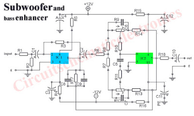
R1 = 22KGood Luck :)
R2 = 100K
R3 = 220R
R4 = 220R
R5 = 220R
R6 = 10K
R7 = 4K7
R8 = 1K
R9 = 20K Trim
R10 = 150K
R11 = 22K
R12 = 20K Trim
R13 = 4K7
R14 =2K2
R15 = 220R
R16 = 220R
R17 = 180K
R18 = 22K
C1 = 4u7/25V
C2 = 10uF/25V
C3 = 220uF/25V
C4 = 220uF/25V
C5 = 1n2
C6 = 47n
C7 = 47n
C8 = 100n
C9 = 100n
C10 = 4u7/25V
C11 = 330uF/25V
C12 = 330uF/25V
IC1 = JRC4558
IC2 = TL074
Sunday, October 6, 2013
Polk Audio 100W Subwoofer
The PSW10 subwoofer fills indoors the foundation outcome of your institution acting usage, so your foremost speakers dont hold to put on deep duty, as an alternative having solitary to procreate the normal and climax frequencies. If youa propos looking pro your original subwoofer, look rejection extra than the PSW10. Its a horrible solution for completing your sound approach and spirit take your viewing experience, movies, games and tube to a top level of enjoyment.
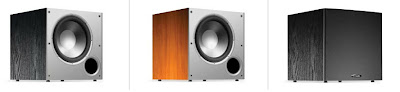
Dynamic Balance® Woofer Design. Polk perfected the method of analyzing a presenters minuscule behavior with laser Interferometry. With with the aim of in sequence during offer, Polk engineers limited the ideal combination of resources, geometry and construction techniques to factually “song unconscious” superfluous resonance. The product is a subwoofer with the intention of delivers innocent, distortion uncontrolled deep low.
Klippel Optimized Woofer. Using a state-of-the-drawing Klippel Distortion Analyzer, Polk engineers optimized the woofers motor form, voice coil alignment and suspension, bringing you the preeminent on the cards performance even next to the generally extreme listening levels.
Composite Polymer funnel We dont expenditure reduced paper cardboard woofers. This is the real deal and part of why the PSW 10 subwoofer outperforms the competition.
Source : Polk Audio 100W Subwoofer
Saturday, September 14, 2013
Subwoofer Speaker box design
The order of 4 or sealed rear chamber bandpass system is essentially a system of watertight enclosures with the addition of an acoustic filter for the driver. The resulting system usually provides a lower cut-off frequency, the compromise that a larger case. The space can be reduced by two drivers in isobaric configuration.
4th-order bandpass systems generally show better able to handle the functions that the other major systems are considered. The transient response and is second only to the sealed enclosure systems, making it a good choice for subwoofer applications.
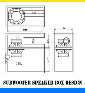 |
| Subwoofer Speaker box design |
Since all output 4th order bandpass system is via the port, the largest diameter possible for the port area should be used to minimize noise from the port. The ports must be incinerated where possible, for the same reasons.
The 4th order bandpass system rarely allows a perfect bandpass response - there is usually an out-of-band noise present in the production. A notch filter can be used simply to reduce the noise as audible. Otherwise, a lowpass filter used in series with the driver, but the in-band response system may be affected if this approach is taken.
As the speaker sound 4th order band pass issued by the openings or ports on the port side of the box, the port noise inevitable.
This unwanted noise can be minimized by a notch filter and the largest diameter possible for the port of the area should definitely be used. Another option is to burn the ports of the 4th order bandpass room as this will certainly help to reduce unwanted extra from the subwoofer.
Subscribe to:
Posts (Atom)