Showing posts with label booster. Show all posts
Showing posts with label booster. Show all posts
Saturday, October 19, 2013
MP3 Player Booster Circuits
MP3 players are all the rage these days. The smaller ones in memory-stick format are particularly easy to take with you; your very own ‘personal sound system’ on the move! It’s when you want others to share your taste in music that you find these players to have a lack of power. You can get round this problem with the help of the MP3 booster, a small amplifier that can be used to connect your MP3 player directly to your Hi-Fi. When you next invite your friends to a party you can ask them to bring their ‘personal music’ as well as the usual drinks!
But first we have to build this booster! The small battery-powered players have an output signal that is more than sufficient to drive a set of 32 Ohm headphones. You’ll often find that with an output of 1mW the sound pressure level (SPL) produced can reach up to 90 dB. This would be sufficient to cause permanent damage to your hearing after only one hour! The maximum output voltage will then be around 200mV. This, however, is insufficient to fully drive a power amplifier. For this you’ll need an extra circuit that boosts the output voltage.
Power amps usually require 1 V for maximum output, hence the signal has to be amplified by a factor of five. We will also have to bear in mind that quieter recordings may need to be amplified even more. We’ve used a simple method here to select the gain, which avoids the use of potentiometers. After all, the MP3 player already has its own volume control. We decided to have two gain settings on the booster, one of three times and the other ten times. Amplifiers IC1A and IC1B (for the right and left channels) are housed in a single package, a TS922IN.
The output signal of the MP3 player is fed via a stereo cable and socket K1 to the inputs of the amplifiers. The gain depends on the relationship between resistors R2 and R1 (R6 and R5 for the other channel) and is equal to ten times. When you add jumper JP1 (JP2), resistor R3 (R7) will be connected in parallel with the negative feedback resistor R1 (R6), which causes the gain to be reduced to about three. When you start using the booster you can decide which gain setting works best for you.
Circuit diagram:
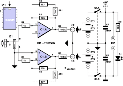
MP3 Booster Circuit Diagram
Resistor R4 (R8) takes the amplified MP3 signal to the output socket K2 (K3). A cable then connects these phono sockets to the input of your power amplifier. The resistors connected in series with the output (R4 and R8) are there to keep the booster stable when a long cable is connected to its output. Cables have an unwelcome, parasitic capacitance. This capacitive effect could (due to phase shifts of the signal) affect the negative feedback of the booster in such a way that a positive feed back occurs, with the result that the booster oscillates and possibly damages the power amplifier!
The resistors (R4 and R8) effectively isolate the output of the booster from the parasitic capacitance of the output cable. They also protect the booster outputs from short circuits. We’ve used a TS922IN opamp in this booster because it can operate at very low supply voltages (the maximum is only 12 V!), but can still output a reasonable current (80 mA max.). For the supply we’ve used rechargeable batteries (e.g. NiCd or NiMH cells) so that we don’t need a mains supply.
To keep the number of cells required as small as possible, we’ve chosen a supply voltage of 5 volt; this can be supplied by four rechargeable batteries. It is also possible to use four ordinary, non-rechargeable batteries; it’s true that the supply voltage then becomes a bit higher (6 Volts), but that won’t cause any harm. Since we’ve used a symmetrical supply for the booster (2 x 2 batteries), it will be easiest if you use two separate battery holders, each with two AA cells. The two holders are connected in series.
Make sure that the batteries are connected the right way round; the positive of one always has to be connected to the negative of the next. This also applies to the connection between the two battery holders. S1A/B is a double pole switch, which is used to turn both halves of the battery supply on or off simultaneously. If you can’t find the (dual) opamp we’ve used (or an equivalent), you could always use standard opamps such as the NE5532, TL082 or TL072. These do need a higher supply voltage to operate properly. In these cases you should use two 9 V batteries and replace resistor R9 with a 15 kΩ one.
Do take care when you connect the circuit to your power amplifier because the output signal can be a lot larger and you could overload the power amplifier. (Although you’re more likely to damage the loudspeakers, rather than the amplifier!) (Please note that these two 9 V batteries can’t be used as a supply for the TS922IN!) In our circuit we’ve used a stereo jack socket for the input and phono sockets for the output because these are the most compatible with MP3 players and power amplifiers respectively. If you wanted to, you could solder shielded cables directly to the circuit instead, with the correct plugs on the ends. You’ll never find yourself without the correct connection leads in that case!
Source: Elektor Electronics 12-2006

Monday, October 7, 2013
Subwoofer booster circuit
Subwoofer booster circuit is used to enanching or boosting or increase the subwoofer amplifier, but it also can improve the quality of the bass sound on an amplifier or High Power Amplifier. Subwoofer booster circui / bass enhancer circuit based on the IC 4558 and TL074 or commonly known as IC op-amp , its suitable to be an boosting in subwoofer system, which together with some components.
For this subwoofer booster / enhancher circuit using voltage of 12 V + , 12V - , and ground. To be in accordance with the power of the speakers and amplifiers , the Subwoofer booster circuit / subwoofer enhancer is also equipped with a subwoofer volume setting on the R9 and R12 use 20 K ohm trimpot. Issued a circuit of subwoofer output is quite high , making it suitable for some speakers.
For this subwoofer booster / enhancher circuit using voltage of 12 V + , 12V - , and ground. To be in accordance with the power of the speakers and amplifiers , the Subwoofer booster circuit / subwoofer enhancer is also equipped with a subwoofer volume setting on the R9 and R12 use 20 K ohm trimpot. Issued a circuit of subwoofer output is quite high , making it suitable for some speakers.
Part List :
Subwoofer booster circuit
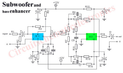
R1 = 22KGood Luck :)
R2 = 100K
R3 = 220R
R4 = 220R
R5 = 220R
R6 = 10K
R7 = 4K7
R8 = 1K
R9 = 20K Trim
R10 = 150K
R11 = 22K
R12 = 20K Trim
R13 = 4K7
R14 =2K2
R15 = 220R
R16 = 220R
R17 = 180K
R18 = 22K
C1 = 4u7/25V
C2 = 10uF/25V
C3 = 220uF/25V
C4 = 220uF/25V
C5 = 1n2
C6 = 47n
C7 = 47n
C8 = 100n
C9 = 100n
C10 = 4u7/25V
C11 = 330uF/25V
C12 = 330uF/25V
IC1 = JRC4558
IC2 = TL074
Subscribe to:
Posts (Atom)