Showing posts with label filter. Show all posts
Showing posts with label filter. Show all posts
Tuesday, December 24, 2013
Stereo tone control with loudness and filter
Tone control circuit is used to adjust the tones before entering the amplifier. Tone control over equipped with a loudness and filter directly without using the switch to disconnected or connected. Part of his filter that is C1 and R1 from ground to input , and for his loudness on the R4 and C3 are connected to the input and then go to VR1. C2 and R3 go from ground to the input . After the input is set by volume or VR1 then procesed again by treebel ie C8 , R13 , R14 , and VR2 . Bass on R10 , R11, R12 , C7 ,C8 , and VR3. For supply voltages has been given a stabilization in Q3. See schematic below :
  |
| Click to view larger |
Part list :
R1 = 100K
R2 = 50K trim
R3 = 22K
R4 = 15K
R5 = 1K
R6 = 4K7
R7 = 330K
R8 = 330K
R9 = 3K3
R10= 5K6
R11= 8K2
R12= 5K6
R13= 1K
R14= 1K
R15= 50K TRIM
R16= 50K TRIM
R17= 330K
R18= 4K7
R19= 47K
R20= 1K
R21= 4K7
R22= 2K2
R23= 100R
R24= 22K
C1 = 15n
C2 = 15n
C3 = 560p
C4 = 4u7
C5 = 33u
C6 = 4n7
C7 = 39n
C8 = 39n
C9 = 4u7
C10=4u7
C11=470u
C12=100u
Q1 = C1815
Q2 = C828
D1 = Green Led
This tone control is suitable with 150W OCL power amplifier type 036.But the schematic is mono, if you need a stereo tone control you must duplicate the components and circuit.
 |
| Installation the stereo tone control |

Thursday, November 7, 2013
Gambar Skema Rangkaian Subwoofer Filter Mobil
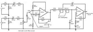 Gambar Skema Rangkaian Subwoofer Filter Mobil
The circuit is designed around the TL072 dual BIFET opamp IC. Out of the two opamps inside the chip, IC1A is wired as a buffer. The left & right audio inputs after mixing is fed to the input of the IC1A using the DPDT switch S1. Switch S1 is the phase control switch which can be used to make the subwoofer in phase with other speakers. When S1 is in position 2, 180 degree phase shift will be induced.POT R7 can be used for controlling the level. IC1B forms the low pass filter whose pass frequency can be controlled by adjusting the dual gang POT R13.
Here is the circuit diagram of a simple subwoofer filter that can be operated from a 12V DC supply. Such a circuit is useful in automobile subwoofer applications. The circuit is nothing but a low pass filter whose pass frequency can be adjusted between 60 to 160 Hz.
Here is the circuit diagram of a simple subwoofer filter that can be operated from a 12V DC supply. Such a circuit is useful in automobile subwoofer applications. The circuit is nothing but a low pass filter whose pass frequency can be adjusted between 60 to 160 Hz.
Saturday, October 26, 2013
Filter PreAmp Subwoofer
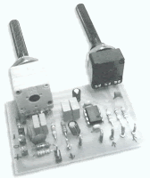
Acoustic spectrum is extended by the 20Hz frequency is very low and reaches as high frequency 20000Hz. In the low frequency is lowered sense of direction. This reasoning leads us to attribute to the speakers use of very low frequency. Making it to you we propose to distinguish these frequencies, in order for him to lead us on a suitable amplifier.
Acoustic filter are met at different points in the sound system. Applications knownest they are filter baxandal to organize low-and high-frequency tones and crossover filter where the acoustics are separated in the subareas, for it leads to the appropriate speakers. Applications that you can we propose is a simple filter that limits the acoustic region (20-20000Hz) in 20-100Hz region.
Acoustic filter are met at different points in the sound system. Applications knownest they are filter baxandal to organize low-and high-frequency tones and crossover filter where the acoustics are separated in the subareas, for it leads to the appropriate speakers. Applications that you can we propose is a simple filter that limits the acoustic region (20-20000Hz) in 20-100Hz region.
With manufacturing, we propose that you can you can make an active filter for you lead a very low frequency loudspeaker. With this you will put a big one between speaker HIFI speakers from you. In order for you to have a complete picture of sound you will need also an appropriate amplifier. In the entry of circuit you will connect the two roads out of the preamplifier or the exit of the preamplifier few. The series production in order to allocate out of the facility led a series of subwoofer power. If for some reason you do not have space for you to put the third speaker in the courtroom, then you can choose a smaller speaker. This output will depend on the type of music that you hear. If in deed you have the space, then after you create a filter and still say thank you, you can he recommend your friends or still makes each other to your friends.
Circuit diagram
 |
| Filter | PreAmp Subwoofer circuit diagram |
Parts
R1 = 39 Kohm
R2 = 39 Kohm
R3 = 47 Kohm
R4 = 10 Ohm
R5 = 22 Kohm
R6 = 4.7 Kohm
R7 = 22 Kohm
R8 = 4.7 Kohm
R9 = 10 Ohm
R10 = 220 Ohm
C1 = 39 pF
C2 = 0.1 UF
C3 = 0.1 UF
C4 = 0.2 UF
C5 = 0.4 UF
C6 = 0.1 UF
C7 = 0.1 UF
IC1 = TL064
In the form that appears theoretical filter circuit. At first glance we see three different circuits which are mainly produced by two rounds of operational amplifiers. This circuit is a mixture, with the assistance variable amplifier and variable filters. Late-making requires a series of operations catering catering with the same trend with  ± 12. operational amplifier which is the active element for this circuit is the type of dual operation as a TL082 and NE5532. The operational amplifier is included in a family is equipped with field-effect transistor IFET in their entries. Each member is allocated a family in bipolar transistor circuits and field effect. This circuit can function in a high inclination, because of their high propensity to use transistors. Also they have the high honor rhythm elevation (slew rate), low polarization at this time for entry and little influenced by temperature. The operational amplifier has an area of 3MHz unity gain bandwidth. Another important element for them is a great choice reject noise, there are currently in the line of catering.
Price refused to greater than 80dB, their consumption is small, from 11 to 3 mA. They briefly sold internally with eight pins and allocate two operational amplifiers, In the same row 14 pin in short they combine four operations, the trade them for sale with code TL074, TL084 and TL064, a nutshell with eight pins they sold the operational amplifier TL071 TL061 kajTL081 . In manufacturing we use the TL082 that has two operational. First operation of TL082 he worked as an amplifier and mixed with two channels, the entry is negative, it is a little mixed with the two resistances. A potentiometer on the steps of determining the aid circuit. At this point the left wing and right-channel preamplifier they added means of two resistances. En operational continuity with the help strengthen the signal is made depending on the price that has been potentiometer.
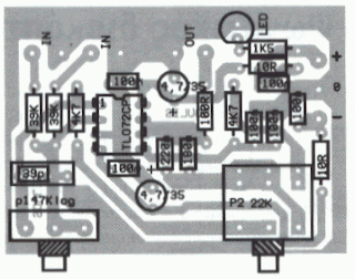 |
| PCB layout |
Place runner comparable with the assistance of the circuit. The second operational amplifier is a filter manufacturing. Filters from the acoustic frequency from second grade and he made a round of operational amplifiers. This filter section with variable frequency low-cut. This frequency can be changed and took the price of very low frequency of 30Hz or still exceeds 150Hz. The frequency of the filter depends on the price cuts that have circuit elements. Change the value of the elements that we can have a frequency cut 150Iz, 130Hz, 100Hz, 7A? Z, 6A? Z even 3A? Z, is the price that they can be achieved by simple rotation of the double potentiometer. Filter circuit has been made about an operation that has completed a TL082 dual operational amplifier. In the filter out we will connect the plug load which is connected amplifier. In a series of exit are presented, which are limited as to the extent of frequency, the signal applied in the entry of the circuit.
Friday, October 18, 2013
300 3400 Hz Second Order Speech Filter
Using two op amps, this filter is designed for second-order response. It has a bandpass of 300 to 3400 Hz, for applications in speech or telephone work.
300-3400 Hz Second Order Speech Filter Schematic

300-3400 Hz Second Order Speech Filter Schematic
Sunday, October 13, 2013
Subwoofer Filter with LM741
The acoustics of converting a filter, near are many aspects of the financially viable possibility of the further famous are Baxandal filter low and soaring frequency filters and crossover Acoustic area is transformed into subordinate-domains, so with the purpose of the Thursday Speakers. Applications, we offer a filter, the limits of the region to transform acoustic (20-20000Hz) happening the region of 20-100Hz.
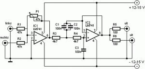
The make signs on behalf of a head high pass filter C1, C2, P1, which is undesirable level DC input. A lowpass filter consisting of R3, R4, C3 prevents frequencies on top of 10 kHz, which look after not benefit from this design, and it would come about so as to the instability and clatter. The precipitate amp invert make signs.
The low Summary of the amplifier signals extend to a next low-pass filter to prevent the frequency from the speakers.
I unambiguous, a second order, because this box with a bunged place bring out. If you give birth to a circuit with a valve coordination, and therefore simply close the Wind (Roll a pair off of socks and pick by the docks / Wind), this preference bequeath you a sealed box as a replacement for.
Saturday, October 12, 2013
Subwoofer Pre Amp Filter
Acoustic spectrum is extended by the 20Hz frequency is very low and reaches as high frequency 20000Hz. In the low frequency is lowered sense of direction. This reasoning leads us to attribute to the speakers use of very low frequency. Making it to you we propose to distinguish these frequencies, in order for him to lead us on a suitable amplifier.
Acoustic filter are met at different points in the sound system. Applications knownest they are filter baxandal to organize low-and high-frequency tones and crossover filter where the acoustics are separated in the subareas, for it leads to the appropriate speakers. Applications that you can we propose is a simple filter that limits the acoustic region (20-20000Hz) in 20-100Hz region.
With manufacturing, we propose that you can you can make an active filter for you lead a very low frequency loudspeaker. With this you will put a big one between speaker HIFI speakers from you. In order for you to have a complete picture of sound you will need also an appropriate amplifier. In the entry of circuit you will connect the two roads out of the preamplifier or the exit of the preamplifier few.
The series production in order to allocate out of the facility led a series of subwoofer power. If for some reason you do not have space for you to put the third speaker in the courtroom, then you can choose a smaller speaker. This output will depend on the type of music that you hear. If in deed you have the space, then after you create a filter and still say thank you, you can he recommend your friends or still makes each other to your friends.
Circuit diagram |
| Filter | PreAmp Subwoofer circuit diagram |
Parts
R1 = 39 Kohm , R2 = 39 Kohm,R3 = 47 Kohm,R4 = 10 Ohm,R5 = 22 Kohm,R6 = 4.7 Kohm,R7 = 22 Kohm, R8 = 4.7 Kohm, R9 = 10 Ohm, R10 = 220 Ohm, C1 = 39 pF,C2 = 0.1 UF,C3 = 0.1 UF, C4 = 0.2 UF, C5 = 0.4 UF, C6 = 0.1, UF C7 = 0.1 UF, IC1 = TL064
In the form that appears theoretical filter circuit. At first glance we see three different circuits which are mainly produced by two rounds of operational amplifiers. This circuit is a mixture, with the assistance variable amplifier and variable filters. Late-making requires a series of operations catering catering with the same trend with  ± 12. operational amplifier which is the active element for this circuit is the type of dual operation as a TL082 and NE5532.
The operational amplifier is included in a family is equipped with field-effect transistor IFET in their entries. Each member is allocated a family in bipolar transistor circuits and field effect. This circuit can function in a high inclination, because of their high propensity to use transistors. Also they have the high honor rhythm elevation (slew rate), low polarization at this time for entry and little influenced by temperature. The operational amplifier has an area of 3MHz unity gain bandwidth. Another important element for them is a great choice reject noise, there are currently in the line of catering.
Price refused to greater than 80dB, their consumption is small, from 11 to 3 mA. They briefly sold internally with eight pins and allocate two operational amplifiers, In the same row 14 pin in short they combine four operations, the trade them for sale with code TL074, TL084 and TL064, a nutshell with eight pins they sold the operational amplifier TL071 TL061 kajTL081 . In manufacturing we use the TL082 that has two operational. First operation of TL082 he worked as an amplifier and mixed with two channels, the entry is negative, it is a little mixed with the two resistances. A potentiometer on the steps of determining the aid circuit. At this point the left wing and right-channel preamplifier they added means of two resistances. En operational continuity with the help strengthen the signal is made depending on the price that has been potentiometer.
|
| PCB layout |
Place runner comparable with the assistance of the circuit. The second operational amplifier is a filter manufacturing. Filters from the acoustic frequency from second grade and he made a round of operational amplifiers. This filter section with variable frequency low-cut. This frequency can be changed and took the price of very low frequency of 30Hz or still exceeds 150Hz. The frequency of the filter depends on the price cuts that have circuit elements. Change the value of the elements that we can have a frequency cut 150Iz, 130Hz, 100Hz, 7A? Z, 6A? Z even 3A? Z, is the price that they can be achieved by simple rotation of the double potentiometer. Filter circuit has been made about an operation that has completed a TL082 dual operational amplifier. In the filter out we will connect the plug load which is connected amplifier. In a series of exit are presented, which are limited as to the extent of frequency, the signal applied in the entry of the circuit.
Subscribe to:
Posts (Atom)