Showing posts with label pulse. Show all posts
Showing posts with label pulse. Show all posts
Friday, December 27, 2013
Inverter 5000W with PWM Pulse Width Modulator
Inverter 5000W with PWM
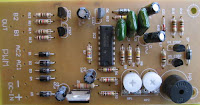
This inverter uses PWM (Pulse Width Modulator) with type IC SG3524. IC serves as a oscillator 50Hz, as a regulator of the desired output voltage. Input power ranging from 250W up to 5000W output and has. Following a series INVERTER 5000W with PWM (Pulse Width Modulator).
 |
| Schematic Inverter 5000W with PWM (Pulse Width Modulator) |
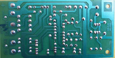 |
| Layout PCB Inverter 5000W with PWM (Pulse Width Modulator) |
below is the output power settings that can be issued by this inverter:
DC voltage and Transformer "T2" winding recommendation:
Winding Power Supply
12VDC 750W P: 24V "12-0-12" / S: 220V
1500W 24VDC P: 48V "24-0-24" / S: 220V
2250w 36VDC P: 72V "36-0-36" / S: 220V
3000w 48VDC P: 96V "48-0-48" / S: 220V
3750w 60VDC P: 120V "60-0-60" / S: 220V
4500w 72VDC P: 144V "72-0-72" / S: 220V
5250w 84VDC P: 168V "84-0-84" / S: 220V
Transformer used is the transformer CT
R1 serves to regulate the voltage to 220v inverter
R2 serves to regulate the inverter output frequency of 50 or 60 Hz (as appropriate)


Saturday, November 2, 2013
Pulse generator circuit with Logic Gate
Pulse generator circuit above is a pulse generator that uses logic gates. There are so many types and variations that can generate a series of pulses.

Next full text...
The simplest is the use of transistors or often called a flip-flop. There also are using integrated circuit such as IC 555. Theres more to exploit the resonance of the capacitor and inductor relationship as oscillators. To be sure whatever form and whatever the circuit components used must be able to generate electric waves which have a peak voltage (logic 1) and valleys (logic 0) is continuous.
Any variation of pulse generator circuit design has advantages and disadvantages of each, just how your decision for the appropriate circuit. For example to create a clock signal for a simple utility that you can only take advantage of the transistor but if you need a more accurate clock signal and form a perfect balance you can use IC Astable or logic gates. Or perhaps you need a signal with very high frequency (up to MHz) you can use a combination of inductor, resistor and capacitor.
Frequency value of the pulse generator circuit gate above is determined by the value kapaitor C2, R2, R3 and VR2. The greater the value of these components will lower the frequency and vice versa. Actually nothing is difficult to make a series of pulse generators, almost all time-based series is utilizing the nature of the charge and discharge capacitor. Therefore, like any form of variations in pulse generator circuit, always have a larger capacitor value will make the frequency produced smaller or longer periods of time, sedangkaan smaller capacitor values will result in greater output frequency.
Thursday, October 17, 2013
Pulse generator circuit with Logic Gate
Pulse generator circuit above is a pulse generator that uses logic gates. There are so many types and variations that can generate a series of pulses.
Next full text...
The simplest is the use of transistors or often called a flip-flop. There also are using integrated circuit such as IC 555. Theres more to exploit the resonance of the capacitor and inductor relationship as oscillators. To be sure whatever form and whatever the circuit components used must be able to generate electric waves which have a peak voltage (logic 1) and valleys (logic 0) is continuous.
Any variation of pulse generator circuit design has advantages and disadvantages of each, just how your decision for the appropriate circuit. For example to create a clock signal for a simple utility that you can only take advantage of the transistor but if you need a more accurate clock signal and form a perfect balance you can use IC Astable or logic gates. Or perhaps you need a signal with very high frequency (up to MHz) you can use a combination of inductor, resistor and capacitor.
Frequency value of the pulse generator circuit gate above is determined by the value kapaitor C2, R2, R3 and VR2. The greater the value of these components will lower the frequency and vice versa. Actually nothing is difficult to make a series of pulse generators, almost all time-based series is utilizing the nature of the charge and discharge capacitor. Therefore, like any form of variations in pulse generator circuit, always have a larger capacitor value will make the frequency produced smaller or longer periods of time, sedangkaan smaller capacitor values will result in greater output frequency.
Subscribe to:
Posts (Atom)