Showing posts with label phone. Show all posts
Showing posts with label phone. Show all posts
Friday, December 27, 2013
Car Mobile Phone Charger Circuit
Cellphone battery charging process when were done traveling is a big problem. Because when traveling source of power supply is generally difficult to find. If you turn on your phone then the battery continuously over time will run out within a period of five to six hours and eventually mobile phones unusable. Here is described a series of simple charger that will increase battery life two to three hours.
In principle, the charger uses a series of Limited Voltage Current Source. Generally requires cellphone battery voltage 3.6 - 6 volts DC and currents 180-200 mA to perform the charging process. Cellphone battery usually consists of three NiCd battery cells, and each cell has a voltage of 1.2 volts potential. At the speed - average low flows required to charge mobile phone battery about - about 100mA.

In this series there is a 12V voltage source consists of 8 regular battery cells (each cell 1.5 Volt) able to supply current at 1.8 A which is connected with output terminals.
The circuit is also able to monitor the battery voltage level which is in charge. And will automatically cut off the charging process when the output terminal detects a certain battery voltage level predetermined. Timer IC NE555 is used to charge and monitor the voltage level in the battery, Pin 5 (IC1) as the control voltage using a reference voltage zener voltage 5.6Volt. Voltage at Pin 6 as the threshold set by VR1 and the voltage at Pin 2 as the trigger is set by VR2.
When the cellphone battery is connected in series (the Charging Process) applied voltage on PIN2 (IC1) as a trigger would be below the value 1 / 3 Vcc and will cause the Flip-Flop in IC1 will ON and on Pin 3 (IC1) will be high (Cause transistor T1 saturation.). When the battery is full (Full Charge) then the voltage will rise and the voltage on the PIN2 (IC1) will be above the level of trigger point threshold. This will cause the Flip Flop OFF and the output will be low (transistor T1 causes the cutoff) and indirectly also the charging process will stop.
Pin 6 (Threshold IC1) is set at 2 / 3 Vcc by using VR1, transistors T1 which is used to increase the charging current. R3 value is very important to provide the charging current, by setting the value of R3 to 39 ohms then the charging current supplied approximately 180mA. This circuit can be built on any type of PCB (General Purpose PCB) for the calibration process using the DC voltage level cutoff Variable Power Supply. Connect the output terminal circuit with Variable DC Power Supply and set on 7 volts. Adjust VR1 in middle position and slowly adjust VR2 until LED1 OFF, this indicates Low Output. LED1 should turn on when the DC Variable Power Supply voltage is reduced below 5V. LED1 Status flame shown in the table below. Closed circuit with plastic casing and use a suitable connector for connecting to the Battery for Mobile.

Sunday, September 29, 2013
Phone Busy Indicator Diagram
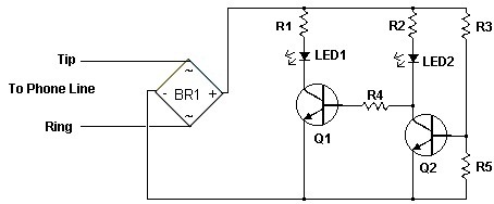 Phone Busy Indicator Diagram
Have you anytime been application the modem or fax and addition abroad picks up the phone, breaking the connection? Well, this simple ambit should put an end to that. It signals that the buzz is in use by lighting a red LED. When the buzz is not in use, a blooming LED is lit. It needs no alien ability and can be affiliated anywhere on the buzz line, alike army central the phone.
Notes
1. This is a very simple circuit and is easily made on a perf board and mounted inside the phone.
2. LED1 and LED2 flash on and off while the phone is ringing.
3. Do not worry about mixing up the Tip and Ring connections.
4. The ring voltage on a phone line is anywhere from 90 to 130 volts. Make sure no one calls while you are making the line connections or youll know it. :-)
5. In some countries or states you will have to ask the phone company before you connect this to the line. It might even require an inspection.
6. If the circuit causes distortion on the phone line, connect a 680 ohm resistor in between one of the incoming line wires and the bridge rectifier.
Phone Busy Indicator Diagram Part List
R1 1 3.3K 1/4 W Resistor
R2 1 33K 1/4 W Resistor
R3 1 56K 1/4 W Resistor
R4 1 22K 1/4 W Resistor
R5 1 4.7K 1/4 W Resistor
Q1, Q2 2 2N3392 NPN Transistor
BR1 1 1.5 Amp 250 PIV Bridge Rectifier
LED1 1 Red LED
LED2 1 Green LED
MISC 1 Wire, Case, Phone Cord
Wednesday, September 11, 2013
Phone busy pointer circuits
Phone circuits are busy pointer. A busy signal is a signal that indicates that someone is trying to call a phone number but could not be contacted because the phone if it is not involved, or because the circuits are busy, calls are impossible to solve.
On many phones, busy signals take the form of a distinctive tone, but a busy signal can also be visual, as in the case yanga phone designed for users of deafness or hearing impairment. Many people are familiar with a busy signal sounds, because significantly different from the dial tone, a tone that indicates that the phone line is open and ready to be called.
In most cases, only a busy signal indicates that the person you are calling is a call. A busy signal will also sound when the phone is turned off. In this case, the signal indicates that there are no technical obstacles to placing the call, but calls can not be completed because the phone is in use.
In some cases, you can ask the operator to enter, if you call in an emergency, in this case the operator will interrupt the call and inquire whether the subject is willing to take your call.
Have you ever use a modem or fax and someone else pick up the phone, disconnect? Phone circuits are busy these simple pointers that will end all that. Menunjukkam phone signal is being used then the red LED. When the phone is not used, the green LED lights up. It does not require external power and can be connected anywhere on the phone line, even mounted inside the phone.
 |
| Phone busy pointer circuits |
List of Components:
R1 = 3.3K 1/4 W Resistor
R2 = 33K 1/4 W Resistor
R3 = 56K 1/4 W Resistor
R4 = 22K 1/4 W Resistor
R5 = 4.7K 1/4 W Resistor
Q1, Q2 = 2N3392 NPN Transistor
BR1 = 1.5 Amp 250 PIV Bridge Rectifier
LED1 = LED red
LED2 = LED green
Others = Wire, Containers, Telephone Cable
This circuit is very simple and easy to make on the board and installed on the phone. Try a series of telephone busy pointer
Subscribe to:
Posts (Atom)