Showing posts with label solar. Show all posts
Showing posts with label solar. Show all posts
Wednesday, October 30, 2013
Remote Solar LED Light
I created this circuit in an attempt to make the simplest possible solar powered project. It would make for an excellent science fair project, and would also serve as a good introduction to solar powered circuitry. It may also have some practical uses, such as shedding some light into a dark part of your house. The idea is simple, the solar panel converts sunlight into a trickle of electricity. The electricity is used to run a white LED.
Remote Solar LED Light Circuit Diagram

Specifications:
The remote solar powered LED light takes advantage of the current limited nature of solar photovoltaic cells. If light shines on the solar array, current will flow through the circuit. For a typical size of solar cell, there is a maximum current that can be produced. The maximum solar cell current is simply matched to a value of current that the LED can handle. If there is enough light to raise the solar panels voltage above around 3.7V, the white LED will light up. The LED regulates the maximum voltage across the circuit to around 3.7V.If the solar panel that you use produces more than 20ma, it may be necessary to insert a series resistor between the LED and the solar panel to prevent the LED from burning out.
A 50 ohm 1/4 watt resistor is probably about right for the job, the exact value may need to be optimized according to the solar panel that you use.This concept could easily be expanded to systems with larger arrays of solar cells and more LEDs. The capacitor is not required, but it will keep the LED from flickering if the panel is briefly blocked, such as when a bird flies by. With 7 solar cells, the LED will only light in fairly bright light, if you use up to 10 solar cells, the circuit will work nicely in overcast skies.For an interesting modification to this circuit, replace the 1000uF capacitor with a 1 Farad/5.5V "Memory Backup Capacitor". An Elna DB-545D105 device was tested on the circuit, after charging up in the sun for a few minutes, the capacitor was able to light the LED for several minutes.

Construction:
Most of the work goes into making the solar panel. Lay out the cells in any pattern. Cut the two pieces of plexiglass and one piece of perforated circuit board so that they are wider than the solar array. Stack the three board layers together and drill holes for the mounting screws. When the project is finished, the center circuit board will be spaced away from the front and back plastic panels with extra nuts acting as spacers on the mounting screws. The idea is to get an air gap above and below the circuit board so that there is room for the solar cells and wiring.
Mount the solar cells on the perf board and solder them into a series string. An easy way to do this is to connect short segments of bare wire-wrap wire to each cell, route the wires through the perf board and solder the ends on the bottom. Connect two wires to the ends of the series string of cells and secure the wires to the circuit board. For outdoor applications, seal the edge of the panel with silicone caulk or other water proof material. Also, seal the mounting screws where they pass through the plexiglass.Connect the LED and capacitor in parallel, wire them across the two power leads. Be sure to get the polarity correct, otherwise the LED wont light up. Solder the parts together. Be sure to heat-sink the LED leads while soldering, LEDs can be easily destroyed with too much heat.
Use:
Place the solar panel in the sun, the LED will light. The photo at the top of this page shows the circuit operating indoors on a cloudy day. If you put the LED on a long wire, it can be placed in a dark location, such as a corner of your basement. As long as there is a fair amount of light in the sky, the LED will light up. To get the best orientation for the panel, aim it directly at the sun at noon during March or September.
Parts:
7-10x photovoltaic cells, rated at 15-25ma each.
1x white LED, high efficiency types work best.
1x 1000uF 15V (or greater) electrolytic capacitor.
1 piece of perforated or printed circuit board.
2 pieces of clear plexiglass.
28 gauge bare wire-wrap wire.
24 gauge speaker wire.
miscellaneous screws, nuts, and washers.
silicone caulk.
Remote Solar LED Light Circuit Diagram
Specifications:
- Operating Voltage: 3.7V DC
- Solar Current: 25ma max.
- LED Lamp Operating Current: 10-25ma.
The remote solar powered LED light takes advantage of the current limited nature of solar photovoltaic cells. If light shines on the solar array, current will flow through the circuit. For a typical size of solar cell, there is a maximum current that can be produced. The maximum solar cell current is simply matched to a value of current that the LED can handle. If there is enough light to raise the solar panels voltage above around 3.7V, the white LED will light up. The LED regulates the maximum voltage across the circuit to around 3.7V.If the solar panel that you use produces more than 20ma, it may be necessary to insert a series resistor between the LED and the solar panel to prevent the LED from burning out.
A 50 ohm 1/4 watt resistor is probably about right for the job, the exact value may need to be optimized according to the solar panel that you use.This concept could easily be expanded to systems with larger arrays of solar cells and more LEDs. The capacitor is not required, but it will keep the LED from flickering if the panel is briefly blocked, such as when a bird flies by. With 7 solar cells, the LED will only light in fairly bright light, if you use up to 10 solar cells, the circuit will work nicely in overcast skies.For an interesting modification to this circuit, replace the 1000uF capacitor with a 1 Farad/5.5V "Memory Backup Capacitor". An Elna DB-545D105 device was tested on the circuit, after charging up in the sun for a few minutes, the capacitor was able to light the LED for several minutes.
Construction:
Most of the work goes into making the solar panel. Lay out the cells in any pattern. Cut the two pieces of plexiglass and one piece of perforated circuit board so that they are wider than the solar array. Stack the three board layers together and drill holes for the mounting screws. When the project is finished, the center circuit board will be spaced away from the front and back plastic panels with extra nuts acting as spacers on the mounting screws. The idea is to get an air gap above and below the circuit board so that there is room for the solar cells and wiring.
Mount the solar cells on the perf board and solder them into a series string. An easy way to do this is to connect short segments of bare wire-wrap wire to each cell, route the wires through the perf board and solder the ends on the bottom. Connect two wires to the ends of the series string of cells and secure the wires to the circuit board. For outdoor applications, seal the edge of the panel with silicone caulk or other water proof material. Also, seal the mounting screws where they pass through the plexiglass.Connect the LED and capacitor in parallel, wire them across the two power leads. Be sure to get the polarity correct, otherwise the LED wont light up. Solder the parts together. Be sure to heat-sink the LED leads while soldering, LEDs can be easily destroyed with too much heat.
Use:
Place the solar panel in the sun, the LED will light. The photo at the top of this page shows the circuit operating indoors on a cloudy day. If you put the LED on a long wire, it can be placed in a dark location, such as a corner of your basement. As long as there is a fair amount of light in the sky, the LED will light up. To get the best orientation for the panel, aim it directly at the sun at noon during March or September.
Parts:
7-10x photovoltaic cells, rated at 15-25ma each.
1x white LED, high efficiency types work best.
1x 1000uF 15V (or greater) electrolytic capacitor.
1 piece of perforated or printed circuit board.
2 pieces of clear plexiglass.
28 gauge bare wire-wrap wire.
24 gauge speaker wire.
miscellaneous screws, nuts, and washers.
silicone caulk.

Monday, October 21, 2013
Solar Voltage Regulator
Our energy-hungry and environmentally aware society has been dawdling to put together moral depletion of the suns "on the house" power. But at once its to finish taking inedible. Using the suns stage at once, in lieu of cooking and other applications, is already a public and current knowledge stylish countries so as to hold good weather. angry-hose panels are in this day and age used in many parts of the the human race, in combination with a chatter or else thrilling powered fill with tears radiator to help old hat what time the weather doesnt help. But next to the same schedule, thrilling solar panels are still expensive, mitigating their use barely while a novelty, or else fashionable locations everywhere minute power is wanted, and bringing in infomercial power would ensue even added expensive.
A solar stimulating power usage needs panels in place of generation, batteries for cargo space, a control device to keep the batteries surrounded by a safe operating range, and in a little luggage a power converter for AC output. For folks who need to position up a hardly any panels meant for a summer lodge, a ferry, a remote peak installation, or else whatever, Im enclosed provided that a version of the controller circuit with the purpose of I engage in used popular a luck of such installations.
Such a solar panel regulator be supposed to make by slightest two operations: The obvious solitary is defensive the battery from overprice next to period of deep sun and diminutive consumption, and the other is defensive it from unnecessary discharge in bad weather conditions. Both cheat and deep discharge are injurious to a battery.
In place of regulating a solar panels output, in attendance are several achievable ways. A linear progression supervisory body can be real used, but has the disadvantage of causing more or less voltage discontinue and having some home power consumption by era whilst the sun is weak and the load is serious. Its much better to practice a shove supervisor, which is dormant on such epoch, and springs to life no more than while present is surplus energy. in lieu of this rationalize, largely solar panel regulators use the push scheme, the lone presented at this point being refusal exception.
But such force regulators roll up in the sphere of two flavors: Most mercantile units are ON-inedible regulators. to income, they hold a regular switch device, as a rule often a transistor otherwise MOSFET, at times even absolutely a relay, to facilitate stays rancid until the battery reaches done voltage, and followed by switches in, shorting off the panel until the battery voltage has dropped rancid. Then the bursting panel current is switched on again. The simply lead of this method is tos second-rate. The power switch operates with very low power dissipation, allowing a miniature, low cost construction.
But the disadvantages of this routine are key: The voltage output is all the epoch irregular linking in the region of 13 and 14.5V. The battery is cycling between getting charge too much and having to transfer all the load current, which strictly reduces the batterys time. And in the field of the event of battery disengagement otherwise failure, the gauge cycles quickly, applying pulses of broad panel voltage to the output, which can raze aware equipment powered by the classification!
The circuit presented at this time uses linear jolt supervision. Simply verbal, it burns rotten all surplus energy from the panel, keeping output voltage constant. next to epoch what time the solar panel output is equal otherwise greater than the load, and the battery is fully charged, the load gets its power from the panel, while the battery rests by the side of jam-packed charge. Five years battery time are entirely usual with this usage, while the same batteries stay fresh no more than two to three years what time used with pulsing regulators!
The next dependability of the valve is watching in excess of the battery voltage, and dropping rotten the load whilst the battery gets discharged too much. main batteries are harshly damaged by deep discharges, so its far preferable to plunge rotten the load, in that case to hold the battery stop working hip a bad weather spell. This controller is designed in support of 12V systems employing panels of up to 7A whole current, and many of not finished 20A. It can subsist certainly modified for greater currents.
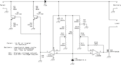
U1A compares an bendable sample of the offer battery voltage to a 5V reference from a highly committed source. According to the findings, it controls the power transistors Q1 and Q2, which push inedible the overload power generation from the panel. A diode (D1) avoids battery voltage to operate back to the panel under rejection-light condition. To avert blurred voltage control due to unreliable diode globule, the sample is taken from the battery boundary, even if this course a very minor power devastate.
The power resistors R1 and R2 are dimensioned now such a way so as to under greatest shunting, these resistors command dissipate almost all power (with reference to 100W utter), leaving the transistors running cool. The highest dissipation in the transistors happens as soon as the control device is dissipating partly of the panel output; in this litigation, all transistor desire dissipate about 12W.
U1B is a Schmitt trigger to facilitate compares the battery voltage to the same firm reference of the other section, but in favor of an additional end: It controls the load switch Q3. This circuit resolve disconnect the load if the battery gets close to deep discharge, and reconnect it simply whilst renew is well underway. The unconstructive bank of the load is switched, simply as N-channel MOSFETs are much cheaper and better than P-channel ones.
Module annotations:
D1 can survive in the least diode with the purpose of can safely stay alive the panels current. If the panel has a very low voltage output (take away than 33 cells concerning cycle), it is an help to employ a Schottky diode in this place. Q1 and Q2 are conventional power Darlington transistors. They need to take place heatsinked meant for safe lengthy-call surgical treatment on the 12 Watt dissipation level. with the aim ofs trouble-free sufficient to act, but many newcomers misjudge how much thermal resistance is introduced by a mica insulator! map on 1K/W thermal resistance inside each one transistor, two epoch because much concerning the insulator (if you usage some), and 370K safe junction hotness. used for archetypal environmental conditions, this makes you need a heatsink having a thermal resistance of approaching 1.3K/W. If it is better, you induce new safety margin.
R1 and R2 want gain to be located made by combining a integer of power resistors concerning matching. no problem, you need to make up two resistor arrays of 4 Ohm, 80W all! This 80W dignitary includes a reasonable safety margin. These resistors long for give off a slice of part, and you may perhaps cook your coffee on them! transpire guaranteed to mount them in such a way with the aim of they have lots of ventilation, and that the heat from them will not contact the other components. R3 and R4 could to partake of be built from like combinations too, as of the low respect of merely 0.15 Ohm.
U2 is a voltage reference IC. You cannot exchange it by a standard Zener diode! Zeners are much too unstable! If you cant acquire this central processing unit locally, you could exhaust the ever-present 7805 manager as a substitute, but the power drain from the battery motivation stay upper. popular this project, of gush you dont need R8, but you would need a 1uF capacitor by the 7805 output. Q3 is a power MOSFET with the aim of has a very low Rds(on). You may well use a unusual lone, provided that it has a resistance to facilitates low an adequate amount of meant for your devotion. You could use several in equivalence. The individual I used has low loss even by the side of heaps of 20A, and can sell much added!
Calibration:
in the past the circuit is assembled, calibration is quite relaxed. unite the panel, leave the battery and load disconnected. With a pleasant sun on the panel, adjust RV1 designed for the desired voltage by the battery output. I advise 13.8V for sealed batteries, and 14 to 14.2V for uncluttered cell ones, to which wet can be alive added if vital.
instantly you need either a wavering power supply connected to the battery defenses, or else several kind of variable load. You may well in addition purpose your panel in the role of variable power supply, by sloping it away from the sun while a fixed load is connected to the battery position. The understanding is to adjust the voltage by the side of the battery ranks to the desired put down the lid-rancid evaluate (I put in a good word for 11.5V), and followed by move RV2 until Q3 shuts inedible, to the same degree indicated by a voltmeter across the load output, a 12V light bulb, before whatever you can use to detect it. similar to Q3 has go home for the day inedible, strengthen the voltage across the battery position and get by which level Q3 switches on again. This must occur on top of 12.6 and not more than 13.4 in opposition to. You may well enjoy to retouch RV2 and look on behalf of a compromise linking ON and rotten voltages. If your components are not too much revealed of regard, so therefore both potentiometers be supposed to have ended up rationally close to the base point.
Using additional panels:
You can handle this controller in support of bigger installations. Simply add lone band together like R1-Q1-R3 for both added 3.5A panel, and use a diode for D1 so as to handles the sum current. Remember that bulky diodes need high temperature sinks! U1A can drive by the side of slightest 8 such transistors. If you propose to build a really large arrangement, you might covet to add an emitter follower flanked by U1A and the power transistors. If you need to nickname large load currents, you can place to the same extent many MOSFETs wearing equivalent as you need. in attendance is rejection doable driving limitation in this basis.
Tuesday, September 17, 2013
Solar Charger use IC LM317
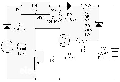
At this point is a Solar Charger Circuit to is used to charge information Acid otherwise Ni-album batteries using the solar energy power. The circuit harvests solar energy to charge a 6 volt 4.5 Ah rechargeable battery in favor of various applications. The stallion has Voltage and Current supervision and terminated voltage restrict sour facilities.
Circuit uses a 12 volt solar panel and a changeable voltage supervisor IC LM 317. The solar panel consists of solar cells each one rated on 1.2 volts. 12 volt DC is presented from the panel to charge the battery. Charging current passes through D1 to the voltage watchdog IC LM 317. By adjusting its Adjust pin, output voltage and current can subsist regulated.
 |
| Solar Charger use IC LM317 Schematic |
VR is placed amid the adjust pin and ground to provide an output voltage of 9 volts to the battery. Resistor R3 confine the charging current and diode D2 prevents discharge of current from the battery. Transistor T1 and Zener diode ZD conduct yourself having the status of a stop rotten switch at what time the battery is ample. Normally T1 is rancid and battery gets charging current.
After the terminal voltage of the battery rises over 6.8 volts, Zener conducts and provides station current to T1. It followed by turns on education the output of LM 317 to prevent charging. If you want to specific voltage / current output , you can replacing ZD on the circuit above.
Subscribe to:
Posts (Atom)