Showing posts with label pcb. Show all posts
Showing posts with label pcb. Show all posts
Monday, December 23, 2013
FM Radio Transmitter schematic with pcb
For those of you like / love to talk in the air can assemble this simple circuit that can be received by the radio receiver to within a few hundred feet. The voice that issues by this circuit at all clear without rustling. Can also be used to link communications over the air using this radio transmitter, provided that other person also had the same circuit.

This PCB design :

Description :
Resistor
R1__________________1K
R2__________________18K
R3__________________82K
R4__________________1K2
R5__________________5K6
R6__________________39K
R7__________________18K
R8__________________68K
R9__________________470R
R10_________________100R
R11_________________50K
XTal
Q1__________________ Crystal according to the desired frequency
Inductor
L1__________________10uH
Capacitor
C1__________________10uF
C2__________________30uF
C3__________________20uF
C4__________________47uF
Transistor
Tr1_________________2SB175
Tr2_________________2SB175
Tr3_________________2SB178
Antenna
X1-1________________10-20 meters
Connector
X2-1________________Ground
X2-2________________VCC 9-12 Volts DC
X3-1________________Input
X3-2________________Ground

Wednesday, October 30, 2013
100W with PCB Power Amplifier Circuit
 |
| High Power Amplifier |
Technical Specifications - Characteristics 100W Power Amplifier :
Output power (f=1 KHz, d=0.5 %): 100 W in 8 ohm
Supply voltage: ................ с 40 V
Quiescent current: ............. 50 mA
Maximum current: ............... 2.6 A
Sensitivity: . 600 mV
Frequency response: ............ 10-35000 Hz (-1 dB)
Distortion HD: ................. 0.01 %
Intermodulation dist.: ......... 0.02 %
Signal/noise: 83 dBConstruction
100W Power Amplifier Circuit Diagram :

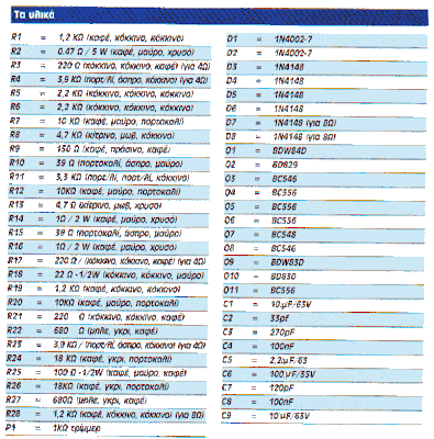
L1 : 10 turns with wire 0,5mm turned on a restistor of 1W
If you use a 4Ohm speaker you will place R3,4,17,23 at the board
If you use a 8Ohm speaker you will place D7 D8 and R28.
For R2 and R16 if you dont find a 0,47Ohm place two of 1 Ohm parallel.
R16 must be 0,47Ohm...the 1Ohm must be a typographical error, take care of this, i havent tested it.
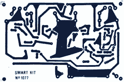
Printed Circuit Board 100W Power Amplifier PCB:

If it does not work :
Check your work for possible dry joints, bridges across adjacent tracks or soldering flux residues that usually cause problems. Check again all the external connections to and from the circuit to see if there is a mistake there.
- See that there are no components missing or inserted in the wrong places.
- Make sure that all the polarised components have been soldered the right way round. - Make sure the supply has the correct voltage and is connected the right way round to your circuit.
- Check your project for faulty or damaged components. If everything checks and your project still fails to work, please contact your retailer and the Smart Kit Service will repair it for you.
source:100W Audio Amplifier
Thursday, September 12, 2013
78XX and 79XX stabilizer circuit with mini PCB design
Here I present the stabilizer circuit of the IC 78XX and 79XX commonly used for voltage stabilization with a mini PCB design , and practical. In the picture above is looking from top the PCB, with a width of 2 cm and 5 cm height. For input voltage can be directly through the AC because ive put it four rectifier diodes are then forwarded to the Elco and IC , that has a stable output in accordance with IC series. What if the IC series 7805 and 7905 , the output voltage of 5 Volts. If the series IC 7812 and 7912 then the output voltage of 12 volts , and so on. See circuit schematic below :


Part List :D1,D2,D3,D4 = 1N4007C1,C2 = 1000 uF/50VC3,C4 = 470 uF/50V
IC1 = 78xx series
IC2 = 79xx series
And this is PCB design look from bottom :

PCB design by SIGMA4-Madiun
Subscribe to:
Posts (Atom)