Monday, December 23, 2013
FM Radio Transmitter schematic with pcb
For those of you like / love to talk in the air can assemble this simple circuit that can be received by the radio receiver to within a few hundred feet. The voice that issues by this circuit at all clear without rustling. Can also be used to link communications over the air using this radio transmitter, provided that other person also had the same circuit.

This PCB design :

Description :
Resistor
R1__________________1K
R2__________________18K
R3__________________82K
R4__________________1K2
R5__________________5K6
R6__________________39K
R7__________________18K
R8__________________68K
R9__________________470R
R10_________________100R
R11_________________50K
XTal
Q1__________________ Crystal according to the desired frequency
Inductor
L1__________________10uH
Capacitor
C1__________________10uF
C2__________________30uF
C3__________________20uF
C4__________________47uF
Transistor
Tr1_________________2SB175
Tr2_________________2SB175
Tr3_________________2SB178
Antenna
X1-1________________10-20 meters
Connector
X2-1________________Ground
X2-2________________VCC 9-12 Volts DC
X3-1________________Input
X3-2________________Ground

Sunday, October 13, 2013
Bully FM radio signals
Interfere with fm radio signal is fun, if youre bored or no work, you can do at home, where neighbors , at school , or even near the transmitter. With the circuit above you can interfere with the speech signal in condenser microphone , and the signal will be issued by the circuit will then be received by FM radio receiver and a voice that we remove it before going out mixed with the signals emitted by radio FM transmitter.


Part List :
R1 = 4K7R2 = 2K2C1 = 1n5C2 = 47pFC3 = 33pFL1 = Nikelin wire coil with a diameter 0,8 mm and 5mm in diameter wound coil 10 xT1 = 2N3906Mic= Condenser Microphone
If the circuit does not work on the errors may occur :
Installation of the opposite transistor , incorrect placement of components , less voltage, the voltage is too high , the microphone is broken, transistor is damaged , broken coil .
Please note this circuit can work and receive FM radio reciver at distance of about 500 meters. And not to much use , because the radio will be able to slam his own neighborhood because they can not listen to good radio . :) good Luck :)
Saturday, October 12, 2013
4 Transistor 500mW FM Transmitter Circuit Diagram
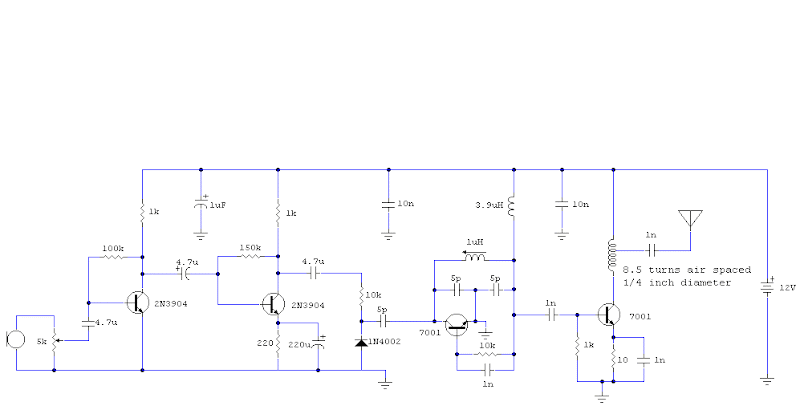 4 Transistor 500mW FM Transmitter Circuit Diagram
As shown, the audio ascribe is a microphone, which uses 2 x 2N3904 as the microphone audio preamplifier. The audio/mic ascribe akin is adjustable by agency of a 5k preset / potentiometer.
The ambit uses a Colpitts oscillator for abundance generation, which is chargeless active and operates at the axiological abundance i.e. no circuitous abundance multiplication or control. The abundance affability basic of the ambit consists of 2 5pF (picoFarad) capacitors and a distinct 10uH (micro-Henry) inductor. These apparatus can be adapted if a change in abundance is appropriate - conceivably alike replaced with capricious capacitors (if youre up to the challenge).
An achievement RF amplifier takes the abundance produced by the Colpitts oscillator and amplifier to about about the 500mW (0.5 Watt) ambit - so this is the almost achievement ability of this FM transmitter. You are brash that back this transmitter operates at the axiological frequency, and because there is no achievement filter, there is acceptable to be some abundance alluvion and harmonics/spurious emissions.
Friday, October 11, 2013
Miniature FM Transmitter

The default for the capacitors type is ceramic, preferably the npo 1% (low noise) type or equivalent. But basically nothing critical here. Use any capacitor you have laying around, but NO electrolytic or tantalum caps. Only if you intend to use this circuit outside the home you may want to select more temperature stable capacitors.
To find the signal on your receiver, make sure there is a signal coming into the microphone, otherwise the circuit wont work. I use an old mechanical alarm clock (you know, with those two large bells on it). I put this clock by the microphone which picks up the loud tick-tock. Im sure you get the idea... Or you can just lightly tap the microphone while searching for the location of the signal on your receiver.
MC2833 FM Transmitter
MC2833 FM Transmitter


The Q1 output transistor is a linear amplifier in the 49.7 MHz and 76 MHz transmitters, and a frequency doubler in the 144 MHz transmitter.All coils used are 7 mm shielded inductors, CoilCraft series M1175A, M1282A–M1289A, M1312A or equivalent.Power output is 9 + 10 dBm for 50 MHz and 76 MHz transmitters, and 9 + 5.0 dBm for the 144 MHz transmitter at VCC = 8.0 V. Power output drops with lower VCC.
Tuesday, October 8, 2013
300m FM Transmitter
300m FM Transmitter Circuit diagram

After the coil in soldered into place spread the coils apart about 0.5 to 1mm so that they are not touching. If you don’t have a trim cap you can use a fixed value capacitor and you can vary the TX frequency by adjusting the spacing of the coils or placing a small piece of ferrite inside the coil , but the better way to change the transmission frequency is to use a variable capacitor .Connect a half or quarter wavelength antenna (length of wire) to the aerial point. At an FM frequency of 100 MHz these lengths are 150 cm and 75 cm respectively.
Sunday, September 29, 2013
87 108MHz FM Wireless Microphone
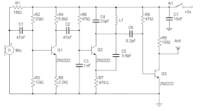
The coil (L1) should be approximately 3 mm in diameter, 5 turns 0.61 mm copper wire. You can vary the Tx frequency by simply adjusting the distance between the coils. The antenna should be a half wavelength or quarter-time (100 MHz, 150 cm or 75 cm).
Parts list:
- T1,T2,T3: 2N2222 transistor
- R1: 10k 5%
- R2: 33k lin.
- R3: 12k 5%
- R4: 5.6k 5%
- R5: 2.2k 5%
- R6,R8: 47k 5%
- R7: 470 ohms 5%
- R9: 180 ohms 5%
- C1,C2: 47nF
- C3: 1nF
- C4: 33pF
- C5: 5.6pF
- C6: 8.2pF
- C7: 10nf
- L1: 3mm in diameter with 5 turns 0.61 mm copper wire
- K1: SPDT toggle switch
- Other parts: 2 AA battery holder, Electret microphone, antenna wire
Wednesday, September 25, 2013
TDA7012T Single chip FM received

Feature contained in FM receiver IC TDA 7012T is quite tempting to an FM receiver. Among features an FM receiver TDA 7012T is a low-voltage applications micro affability arrangement (MTS), Frequency Loked Loop (FLL) to 76 KHz range and selectivity of FM receiver with RC Filter. In an article by FM Radio Receiver IC TDA 7012T can be seen in the FM receiver circuit which can be made.
 |
| TDA7012T- Mini FM received Schematic |
Wednesday, September 11, 2013
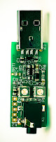
USB FM transmitter circuit
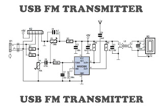 |
| USB FM transmitter schematics |
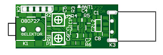 |
| Layout PCB USB FM transmitter |
Capacitors (all SMD 0805)
source [ Link ]