Showing posts with label switch. Show all posts
Showing posts with label switch. Show all posts
Tuesday, December 24, 2013
Sound Operated Switch
This sensitive sound operated switch can be used with a dynamic microphone insert as above, or be used with an electret (ECM) microphone. If an ECM is used then R1 (shown dotted) will need to be included. A suitable value would be between 2.2k and 10kohms.
Sound Operated Switch Circuit diagram

The two BC109C transitors form an audio preamp, the gain of which is controlled by the 10k preset. The output is further amplified by a BC182B transistor. To prevent instability the preamp is decoupled with a 100u capacitor and 1k resistor. The audio voltage at the collector of the BC182B is rectified by the two 1N4148 diodes and 4.7u capacitor. This dc voltage will directly drive the BC212B transistor and operate the relay and LED.
It should be noted that this circuit does not "latch". The relay and LED operate momentarily in response to audio peaks.
Sound Operated Switch Circuit diagram
It should be noted that this circuit does not "latch". The relay and LED operate momentarily in response to audio peaks.

Wednesday, November 6, 2013
Touch Switch Using FET
The series of touch this switch be an Touch Switch made using FET. This circuit serves to activate electronic devices only when we touch touch sensors.
Once we release a touch to the sensor, the electronic device that is connected is turned off again. The series of touch switch or touch switch is very simple, composed only of a FET, resistor and capacitor. The series of touch switches / touch switches work with source voltage 12VDC. Detailed series of touch switches / touch switch can be seen in thethe following figure .
Once we release a touch to the sensor, the electronic device that is connected is turned off again. The series of touch switch or touch switch is very simple, composed only of a FET, resistor and capacitor. The series of touch switches / touch switches work with source voltage 12VDC. Detailed series of touch switches / touch switch can be seen in thethe following figure .
FET Touch Switch
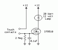
The series of touch switches / touch switch can only be used to illuminate DC, 12V DC lamp when it replaced the relay, the circuit can be used safely to load the AC network. Sensor touch to this series was made with 2 pieces of plate are arranged close together (within 1-2mm).
Monday, November 4, 2013
Light Switch Circuit Diagram
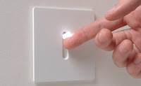
The series of light switches this time slightly different from the voltage of work. The series of light switches can work directly on the AC power network. Light switches are using the main component of TRIAC and LDR. The circuit is very simple and the components were sold in the market.
If you want a light reception sensitivity of this circuit can be arranged then the 3.3 MOhm resistor can be replaced with a variable resistor. For more details can be seen from the following series of images.
If you want a light reception sensitivity of this circuit can be arranged then the 3.3 MOhm resistor can be replaced with a variable resistor. For more details can be seen from the following series of images.
 |
| Circuit Diagram |
With Triac Light Switch series is prisipkerjanya as dimers, but dimers control performed by the reception of light around the LDR. The lower the intensity cayaha received LDR then semkin bright lights. For installation LDR need to be considered so as not exposed to light from the lamp directly.
Wednesday, September 25, 2013
Light Switch Circuit Diagram
The series of light switches this time slightly different from the voltage of work. The series of light switches can work directly on the AC power network. Light switches are using the main component of TRIAC and LDR. The circuit is very simple and the components were sold in the market.
If you want a light reception sensitivity of this circuit can be arranged then the 3.3 MOhm resistor can be replaced with a variable resistor. For more details can be seen from the following series of images.
If you want a light reception sensitivity of this circuit can be arranged then the 3.3 MOhm resistor can be replaced with a variable resistor. For more details can be seen from the following series of images.
|
| Circuit Diagram |
With Triac Light Switch series is prisipkerjanya as dimers, but dimers control performed by the reception of light around the LDR. The lower the intensity cayaha received LDR then semkin bright lights. For installation LDR need to be considered so as not exposed to light from the lamp directly.
Wednesday, September 11, 2013
Toggle switch with Infra Red IR
Toggle switch in this article is a series of toggle switches that are controlled by infrared light. The series toggle switch is made from a combination of data flip-flop CD4013 2 units.
Receiver circuit of the infrared light signals arranged with infrared receiver as found on television remote receiver. Infrared signal from remote is used as clock signals and data to the data flip-flop first. then the second flip-flop data set as a toggle flip-flop toggle the output signal is used to drive the relay. for more details can be seen in thethe following image .
Receiver circuit of the infrared light signals arranged with infrared receiver as found on television remote receiver. Infrared signal from remote is used as clock signals and data to the data flip-flop first. then the second flip-flop data set as a toggle flip-flop toggle the output signal is used to drive the relay. for more details can be seen in thethe following image .
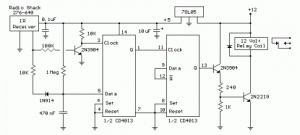
Series Toggle Switch With Infra Red (IR) that is required to supply voltage range of 12VDC and the output of Toggle Switch With Infra Red (IR) is dapt used to turn on the lights or other electronic devices with DC or AC voltage source. Series Toggle Switch With Infra Red (IR) was isolated from the load that is placed for use as the final relay.
Subscribe to:
Posts (Atom)