Monday, September 30, 2013
AM Radio Receiver Using by TEA5551T
Using TEA5551T monolithic integrated radio circuit can be designed a AM radio receiver circuit which is designed for use as a portable radio receiver with headphones .
AM Radio Receiver Circuit diagram

The TEA5551T radio receiver circuit contains all is needed for a AM radio receiver circuit (a complete AM part and dual AF amplifier with low quiescent current).The TEA5551T support a input voltage range (VS) from 1.8 V to 4.5 V but the typical voltage is 3 volts .Because in most case we don’t find to buy inductors you need to build the inductors L1 , L2 , L3 . In the picture bellow you can see the construction data for these three inductors .
AM Radio Receiver Circuit diagram
The TEA5551T radio receiver circuit contains all is needed for a AM radio receiver circuit (a complete AM part and dual AF amplifier with low quiescent current).The TEA5551T support a input voltage range (VS) from 1.8 V to 4.5 V but the typical voltage is 3 volts .Because in most case we don’t find to buy inductors you need to build the inductors L1 , L2 , L3 . In the picture bellow you can see the construction data for these three inductors .
Building a radio station
Requires us to make things systematically and efficiently, because time is very valuable to us, then some of the advances in technology has been applied in various fields, including education, because this is where all the technological advances developed. Lots of technology is rapidly expanding in our country today. With technology growing by leaps and bounds this is what will make the work more systematic and efficient. Based on our technological advances and his friends create a system are related to the Electronics course, we propose the same faculty to develop a community tool. We got a second job in four semesters, which makes the FM transmitter.
Departing from hobby assembling electronic items, we try to assemble a mini-power transmitter that can emit a short signal of approximately 100 meters with power (power) 5 watts. This is a pilot who later became 12 watts. With 12 watts of power, radio broadcasts to reach a village.
1.2 Formulation of Problem Problems are handled from this lab assignment is to create and analyze the quality of an FM transmitter to get the data at test point 1, point 2 test, test point 3 and the exact frequency as desired. Things are of practical tasks is restricted only to analyze the quality of a transmitter and retrieve data from an existing test point.
1.3 Limitations Problems to be addressed in this lab assignment is limited to some of the following: 1 • Retrieving data from the frequency and calculate TP 1 to TP 3. 2 • Analyze a transmitter in the room, based on measurement data and make conclusions.
1.4 Objectives Objectives to be achieved in this task are: A. Students can design and make the circuit in fm transmitter. 2. 12 Watt FM transmitter that can be made of appropriate tools and can be marketed.
1.5 Methodology In completing this lab assignment, the steps are as follows: 1 • Learn about basic electronics concepts and learn concepts about the mechanism of FM modulation. 2 • Analyze and conclude the experimental results, and give advice when it is applied to the practical task of the real system. 3 • Preparing a report on second semester practicum assignment.
1.6 Discussion This book of this lab assignment consists of 5 (five) chapters, in each chapter related to one another, namely:
CHAPTER 1: Provide background on the issues, goals, problems and constraints of the problems discussed in this lab assignment. CHAPTER 2: Provide the theoretical basis to support problem solving in this lab assignment. The basic theory is given include: the mechanism of the tool in used in making the FM transmitter
CHAPTER 3: Planning and manufacture of tools and how each blog diagram contained in FM transmitter CHAPTER 4: Contains the results of calculations and data processing, and analysis results calculation. CHAPTER 5: Provide conclusions about the results already obtained and suggestions. CHAPTER II BASIC THEORY
2.1 Koker

Koker serves to regulate or determine the frequency of the radio transmitter. In koker also Ferrite that serves as a core inductor in addition there is an inductance coil comprising primary and secondary winding. Way of working is to facilitate search koker empty wave. When filling koker in turn to the right to a maximum frequency of the oscillator produce more low. If the FM transmitter lights, turn left up the core koker to hissing on the FM radio signal is lost it will be found a strong and stable.
2.2 Inductor

2.3 Transistor

Transistors have two connections, one of which is the emitter and the other base and collector. Because this is a transistor as two diodes. ransistor C1970 type normally used to raise the voltage 0.8 to 1 watt, I think it was in the C1970 study could increase about 8 times. On the C1971 transistor can be coupled directly from the exciter circuit and the voltage of 6.5 to 7 watts or bias raised about 10 times. If the C1970 to C1971 join the output power of about 12 watts or more. (All will be explained in Chapter III)
Transistors have two connections, one of which is the emitter and the other base and collector. Because this is a transistor as two diodes. ransistor C1970 type normally used to raise the voltage 0.8 to 1 watt, I think it was in the C1970 study could increase about 8 times. On the C1971 transistor can be coupled directly from the exciter circuit and the voltage of 6.5 to 7 watts or bias raised about 10 times. If the C1970 to C1971 join the output power of about 12 watts or more. (All will be explained in Chapter III)
2.4 Exciter Exciter circuit consists of an oscillator and buffer. • Oscillator Transmitter is the core of an oscillator. To be able to build a good communication system should begin with an oscillator that can work perfectly. In the communication system, the oscillator generates a sine wave is used as the carrier signal. Then the information signal is superimposed on a carrier signal with the modulation process. • Buffer (Buffer) All types of oscillators require a buffer. Buffer serves to stabilize the frequency and / or amplitude of the oscillator from loading the next level. Usually a buffer consisting of 1 or 2 levels of the transistor amplifier dibias as class A. The heart of the broadcast transmitter FM exciter is located on it. Function of the exciter is to generate and modulate a carrier wave with one or more input (mono, stereo, SCA) in accordance with FCC standards. Which has been modulated carrier wave is then amplified by a wideband amplifier to the level required by the next level.
2.5 Booster Power amplifier is more popularly known as Booster. Booster is a device mounted radio transmitters attached to and used to amplify radio frequency transmit power in any direction that you want to go. For example, for a transmitter power of 25 watts which include only a single village, Booster is used to transmit power to be 50 to 100 watts so it can be surrounding the district. Boosters are generally small squares connected by cable to the transmitter which he built. Power amplifier is divided into two. First, the power amplifier which amplifies the signal in one cycle, the best signal quality and harmonious. The second, which only reinforces the power amplifier input signal is less than half of the cycle and generate a wave that damaged the same frequency.

Antenna function and simultaneously capture signals radiate radio wave radiation. The antenna is divided into two by the beam, ie • omnidirectional (all directions). This antenna radiates radio waves are equally strong all directions. • Bidirectional (both directions). This antenna radiates equally strong radio waves to only two directions. Two parameters that need to be considered is the polarization of the antenna and its gain. Put simply, an antenna has vertical polarization if the antenna is placed in a position perpendicular to the earth. Antenna with vertical polarization would produce radio waves with vertical polarization as well. In addition to the vertical, some horizontal polarized antenna, when the antenna is positioned parallel to the field of the earth.
2.7 Transmission Line Transmission line is the introduction to the generated power to the transmitter antenna. As an introduction to power, a good transmission line will not reduce the power of delivery and did not radiate, because it is the duty antennas radiate. So that the maximum power transfer occurs, then the transmission line characteristic impedance should also have the same view of resource load. Transmission line characteristic impedance is 300 W common (ribbon cable to the black and white TV), 75 W (on a color TV coaxial cable) and 50W (coaxial cable to the amateur radio equipment). Additional tools are in need in assembling a 12-watt FM transmitter, among which are:
• Power Meter Power Meter is a tool to measure the wave. On a transmission line that is not worth it, but the waves come rolling waves are reflected. Wave dating from the source to the load direction (from transmitter to antenna), while the reflected wave from the opposite direction (from the antenna to the transmitter). Usually on the Power Meter has two scales, one came to power and one for the reflected power. The reflected power scale to be smaller than the scale for the future.
• SWR Meter SWR meter or measuring comparative standing waves are used to measure the ratio of the incident wave and reflected wave. So it is known how a resource commensurate with the burden. The working principle is based on the Power Meter SWR Meter. If there is only one Power Meter measurements, the SWR can be calculated from the incident power (Pf) and the reflected power (Pr) with the formula: SWR = (OPF + ÖPr) (OPF - ÖPr).
• From the formula, the state equivalent (Pr = O) will be obtained SWR = 1.• For a state that is not worth going to get SWR> 1.
• For the worst circumstances in which all power is reflected back dating (Pf = Pr) will get the SWR = infinity.
• Dummy Load To be able to broadcast a maximum transmit power, but efficient, it takes a load impedance that is known with certainty as it is called Dummy Load reference. Dummy Load is free from the influence of frequency and can handle the disposal of the transmit power is too great. Dummy Load impedance is usually 50 or 75 Ohm. Dummy Load can be made with put some resistors in parallel in order to obtain the desired resistance and power. Parallelize some resistors minimize the stray inductance of the resistor. For example, can use the carbon resistor 300 Ohm / 2 watt for 6 seeds that are connected in parallel to get the Dummy Load with power of 12 watts and 50 Ohm impedance.
CHAPTER III PLANNING AND DEVELOPMENT TOOLS
3.1. Preliminary To plan and create a 12 Watt FM transmitter, need to know first about a block diagram of the system, the working system of the circuit is Overall, the calculations and planning.
3.2. System Block Diagram and Figure Series Overall 
The picture above shows a block diagram of this system and image The overall network is made in full. Transmission System Block Diagram picture as a whole

3.2.1 Block diagram of the image transmitter exciter circuit FM

Picture Exciter Circuit Network consists of exciter oscillator and buffer. In this Exciter Network using the specification of components as follows: • Koker • Inductor: L2 = 0.12 micro-Henry, Henry Micro L3 = 0.12, L4 = 0.2 micro-Henry • Transistor: C930 • Ohm: 5.6 K, 47 K, 33 K • Babysitter WANTED: 2.2 nF, 100 nF, 18 pF, 20 pF, 5 pF • trimer: 5-60 pF Exciter is a network that produces oscillations, because the exciter are oscillator that acts as a sine wave generator and it will be dimodulasikan. In the oscillator system is also available buffer (buffer) that functions to stabilize the frequency / modulation oscillator amplifier due to the loading process by the next level.
3.2.2 Network Booster (Power Amplifier)

The series of images Booster In the Booster circuit uses components with the following specifications:
• Inductors: L1 = 0.2 micro-Henry. L2 = 0.2 micro-Henry. 0085 L3 = L4 = 0.04 micro micro Henry Henry. L5 = 0.1 micro-Henry. L6 = 0.2 micro-Henry L7 = 0.2 micro-Henry.
• Transistor 1970: 10 V VCE Ic 0.1 A Β 10-180
• trimer: 5-30 pF Booster circuit consists of two levels of transistor amplifiers, each working on a class C, each input and output transistor amplifier circuit is given impedance adjustment. Strengthening of the first transistor using C1970. Strengthening the circuit has a 9.2 dB power gain (8 times), so that from the exciter-power 0.25 W of power generated should be 2 W. In fact the output of this first level of reinforcement produces only 1.75 Watt power, this is due to the loss of matching network circuit. Strengthening of the second level using transistor C1971. The amplifier circuit has a 10dB power gain (10 times). So that the power of the first level of 1.75 W can be strengthened to 17.5 W. In fact strengthening the power of the second level only reached 12.5 Watt.
This is due to the loss of matching network and the limited range of C1971 transistor. Because the price of the C1971 transistor is relatively expensive it is to use only the C1970 transistor. Therefore, the power generated by the transmitter is not as high as 12 Watt. Because of the heat generated second transistor is large enough then we put enough cooling.
CHAPTER IV TESTING TOOLS 4.1
General This chapter discusses the testing and analysis system that has been made. In general, this test aims to determine if the device has been realized that can be worked in accordance with a predetermined plan specifications. The purpose of the tests performed on the system are as follows:
• Knowing how the exciter circuit
• Knowing how the booster circuit
4.2 Testing exciter circuit
• The purpose To find out if the oscillator can work well and achieve the desired frequency. And also to determine whether the buffer is running properly.
• The equipment used A. Koker 2. Inductor 3. Transistor 4. Resistor 5. Trimer 6. Dummy Load 7. 5 volt power supply 8. Multimeter 9. Frequency Counter 10. PCB
• The test procedure Test Block Diagram A. Assemble the equipment used in accordance Picture 2. Provide 12 volt power supply to the exciter circuit 3. Switch the exciter circuit to get the most power in large 4. Calculate the voltage at TP 1, TP 2 and, TP 3 5. Observe the output (at V output)
• The test results The test results are shown in Table. the following: Exciter circuit Testing Results Test Results Point A 0.6V 2 0.6V 3 11.75 V
4.3 Testing a series of booster
• The purpose To gain greater power and also increase the distance range of further emission up to 7-fold.
• The equipment used A. Inductor 2. Transistor 3. Trimer 4. Dummy Load 5. 12 Volt Power Supply
• The test procedure Testing Block Diagram Picture Booster: A. Assemble the equipment used in accordance Picture 2. Large test circuit voltage that can be accepted 3. Observing the output
• The test results The test results are shown in Table. the following: Booster circuit Testing Results Test Results Point 4 11,75 5 11,75
CHAPTER V CLOSING
5.1. Conclusion Based on the test results it can be concluded:
• In a series of FM transmitters weve made, the power output is only 2 Watt for C1970 transistor used is that only 1 Watt power up
• FM transmitter that can be made only reach 93 MHz frequency
• The distance achieved depends on the power emitted by the FM transmitter
5.2 Advice
• If you want to make the transmitter starts with a good oscillator.
• If you want to make a series of FM with a power greater then use the transistor C1971, C1946. the power generated about 25 watts.
• To balance the output of the FM transmitter mounted circuit PLL (Phase Local Loop).
STK 4050 200Watt Power Amplifier Circuit

Amplifier circuit with IC STK is tough and good quality. In this article an amplifier circuit with IC STK another base. Power "Amplifier 200Watt By STK4050" is an audio amplifier of the STK family with 200Watt power. To create a power amplifier with the STK4050 IC is not require many external components.
Power Amplifier uses symmetric 30Volt power supply system. Power Amplifier With this STK4050 can reproduce the power 200 Watts at 8 Ohm load spaker. In making Power Amplifier 200Watt With this STK4050 do not forget to provide adequate heat sink for the IC STK 4050 in order to avoid overheating.
 |
| Schematics Amplifier STK4050-STK4046 |
 |
| PCB Layout Amplifier |
Series Power Supply for Power Amplifier 200Watt By STK4050 been displayed in one image with a series of "Power Amplifier" 200Watt With STK4050 above. IC STK 4050 in this series there are several types on the market including STK4050II, STK4050V and STK4050.
And below is a list of STK ICs are used for a good quality amplifier.
 |
| Datasheet STK IC Amplifier |
LED Power Meter
LED power Meter circuit is a simple RF detector using diodes to charge a capacitor. The voltage developed across the capacitor is indicated by a multimeter set to a low voltage range. The circuit is soldered together without the need for a PC board, as can be seen in the diagram below and paper clips are used for the positive and negative terminals of the multimeter.

The level power output of an FM transmitter is indicated by the illumination of a LED and the voltage reading on the multimeter gives a further indication of the output.
A digital multimeter may be used but the presence of RF may produce a false reading. Likewise, the radiated energy may upset some analogue meters and you may get full scale deflection on the 15v range as well as the 250v range! But the LED wont lie. It will accurately indicate the RF and you can see the change in brightness as you adjust the coils in the output stage. Some of the cheapest and simplest multimeters will give the best results as they have a low sensitivity and the radiated RF energy will not induce a reading. Even a damaged multimeter can be used, provided the 10v or 15v DC scale is operating.
The reading is not calibrated and does not represent milliwatts output. It is only a visual indication.
We have designed over 10 FM transmitters for inclusion in the pages of this e-magazine and each one has different features and characteristics. Some are designed for 3v operation, some are for 9v operation, some are stable for hand-held situations and others are designed for high output. The illumination of the LED will range from barely visible to very bright.
LED Power Meter Parts
1 - 470R
1 - 100p ceramic
1 - 100n ceramic
2 - 1N 4148 diodes
1 - 5mm Red LED
1 - 2in (5cm) hook-up wire
2 - paper clips
No PC board required
Sunday, September 29, 2013
87 108MHz FM Wireless Microphone
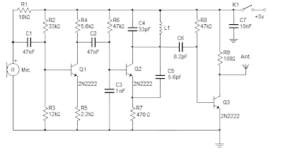
This FM wireless microphone is easy to build and has a useful range of transmission (over 300 meters outdoors). Despite its small number of components and an operating voltage of 3V to easily penetrate over three floors of an apartment building. You can tune anywhere on the FM band (87-108MHz) and its transmissions can be picked up at any point of view of the FM receiver.
The coil (L1) should be approximately 3 mm in diameter, 5 turns 0.61 mm copper wire. You can vary the Tx frequency by simply adjusting the distance between the coils. The antenna should be a half wavelength or quarter-time (100 MHz, 150 cm or 75 cm).
Parts list:
The coil (L1) should be approximately 3 mm in diameter, 5 turns 0.61 mm copper wire. You can vary the Tx frequency by simply adjusting the distance between the coils. The antenna should be a half wavelength or quarter-time (100 MHz, 150 cm or 75 cm).
Parts list:
- T1,T2,T3: 2N2222 transistor
- R1: 10k 5%
- R2: 33k lin.
- R3: 12k 5%
- R4: 5.6k 5%
- R5: 2.2k 5%
- R6,R8: 47k 5%
- R7: 470 ohms 5%
- R9: 180 ohms 5%
- C1,C2: 47nF
- C3: 1nF
- C4: 33pF
- C5: 5.6pF
- C6: 8.2pF
- C7: 10nf
- L1: 3mm in diameter with 5 turns 0.61 mm copper wire
- K1: SPDT toggle switch
- Other parts: 2 AA battery holder, Electret microphone, antenna wire
3 Watt stereo amplifier circuit
3 Watt stereo amplifier circuit using MAX 7910 IC. The MAX9710 a stereo audio power amplifier IC capable of delivering 3Watts of out put to 4 Ohm loads. MAX9710 can be operated from a single 4.5V to 5.5V power supply , makes it ideal for hand held applications.The IC for 3 Watt stereo amplifier circuit also features thermal overload protection.
Circuit Schematics 3 Watt Stereo Amplifier MAX 7910
 |
| 3 Watt stereo amplifier circuit |
This 3 Watt stereo amplifier circuit is suitable for small power audio devices such as radio sets and portable CD players. 5 V DC power supply is used for powering the 3 Watt stereo amplifier circuit. 6V battery with an IN 4007 diode series to the positive terminal of it can also be used instead of 5 V DC supply. The 3 Watt stereo amplifier circuit will get a supply voltage approximately 5 V after 0.7 V voltage drop across diode.
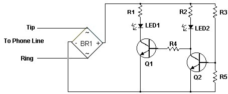
Phone Busy Indicator Diagram
 Phone Busy Indicator Diagram
Have you anytime been application the modem or fax and addition abroad picks up the phone, breaking the connection? Well, this simple ambit should put an end to that. It signals that the buzz is in use by lighting a red LED. When the buzz is not in use, a blooming LED is lit. It needs no alien ability and can be affiliated anywhere on the buzz line, alike army central the phone.
Notes
1. This is a very simple circuit and is easily made on a perf board and mounted inside the phone.
2. LED1 and LED2 flash on and off while the phone is ringing.
3. Do not worry about mixing up the Tip and Ring connections.
4. The ring voltage on a phone line is anywhere from 90 to 130 volts. Make sure no one calls while you are making the line connections or youll know it. :-)
5. In some countries or states you will have to ask the phone company before you connect this to the line. It might even require an inspection.
6. If the circuit causes distortion on the phone line, connect a 680 ohm resistor in between one of the incoming line wires and the bridge rectifier.
Phone Busy Indicator Diagram Part List
R1 1 3.3K 1/4 W Resistor
R2 1 33K 1/4 W Resistor
R3 1 56K 1/4 W Resistor
R4 1 22K 1/4 W Resistor
R5 1 4.7K 1/4 W Resistor
Q1, Q2 2 2N3392 NPN Transistor
BR1 1 1.5 Amp 250 PIV Bridge Rectifier
LED1 1 Red LED
LED2 1 Green LED
MISC 1 Wire, Case, Phone Cord
Mini and simple power amplifier circuits

What is the meaning of the picture above? The above picture is a miniature audio amplifier and very simple. Here I will give an audio amplifier schematic is very simple which only requires a few components only, can be seen under this scheme.

See from above scheme may occur to you, certainly cheap enough to make this amplifier and quite easy to make. The above simple audio amplifier circuit using an IC as the main amplifier and accompanied by other components. IC used is S1513, which requires a supply voltage ranging from 1.5 volts to 6 volts. And only 0.1 W output power with 4 ohm impedance. For a list components can be seen below.
Part list
C1 = 100nF
C2 = 100uF
C2 = 100uF
C3 = 3n3F
C4 = 1uF
C5 = 1uF
U1 = S1513
C5 = 1uF
U1 = S1513
Saturday, September 28, 2013
Heat Sensor Fire Detector Pyroelectric

These sensors form of Lithium Tantalate pyroelectric parallel opposed dual element high gain detector with integrated analog signal processing. These sensors can detect heat changes from -40 to +70 degrees Celsius without change siginfikan of noise and sensitivity.
To use heat sensor pyroelectric detectors Eltec E442-3, it can take a kind of cone is covered with a fresnel lens to focus the direction of the infrared ray IR. Heat sensors then pyroelectric detectors Eltec E442-3 inserted into the cone is then connected to the microcontroller. Analog output value signals which when detects heat, the sensor will cause a drastic change in output voltage.
TDA7275A DC Speed Controller
Using the TDA7275A linear integrated circuit manufactured in a minidip plastic package can be designed a very simple speed regulator electronic project that can be used for speed regulation of small DC motors .

TDA7275A DC speed controller project is intended for use as speed regulator for DC motors of record players, tape and cassette recorders. This DC motor speed controller circuit project can provide a maximum output current of 1.5 amperes .
This circuit can be powered with a voltage range between 8 and 18 volts . V2 is typically 1.5 volt for Motor ”Run” (Acc. Following data or open) and 1 volt for Motor ”Stop” (Acc. Following data or grounded) .
TDA7275A DC Speed Controller Schematic
This circuit can be powered with a voltage range between 8 and 18 volts . V2 is typically 1.5 volt for Motor ”Run” (Acc. Following data or open) and 1 volt for Motor ”Stop” (Acc. Following data or grounded) .
Voltage regulator with LT1086
One way to provide good negative-voltage regulation is with a low-drop-out positive-voltage regulator operating from a well-isolated secondary winding of a switch-mode circuit transformer. The technique works with low-dropout types.Under all loading conditions , the minimum voltage difference between the regulator Vin and Vout pins must be at least 1.5V , IC LT1086 low-dropout voltage. If this requirement isnt met, the output falls out of regulation. Two programming resistors, R1 and R2, set the output voltage 12V, and the IC LT1086 servo the voltage between the output and its adjusting terminals to 1.25V. Capacitor C1 improves ripple rejection, and protection diode D1 eliminates common-load problems.Since a secondary winding is galvanically isolated , a regulator 12V output can be referenced to ground. Therefore , in the case of a negative-voltage output , the positive-voltage terminal of the regulator connects to ground , and the 12V output comes off the anode of D1. The Vin terminal floats at 1.5V ore above ground.

2 X 0 6W schematic audio amplifier
This schematic have require minimum voltage at 1Volt and maximum volotage at 9 Volt. Maximum output power 2 X 0.6W.

Part List:
Capacitor
C1 = 100uF
C2 = 220uF
C3 = 220uF
C4 = 220uF
C5 = 220uF
IC = ULN3782
Friday, September 27, 2013
50W audio amplifier with ICs

The above amplifier circuit based on IC is STK075G, and another equation that is STK084G, STK085, STK086G. and among ic I mentioned that I recommend using ic high supply voltage and high output power and good quality. You can see every ic datasheet at Alldatasheet.com above. Supply voltage between 20 to 55 Volt DC.Part List
R1 = 1K
R2 = 100R
R3 = 100R
R4 = 4.7R
R5 = 56K
R6 = 47R
C1 = 1uF
C2 = 470pF
C3 = 100uF
C4 = 100uF
C5 = 1800pF
C6 = 1uF
C7 = 1800pF
C8 = 0.047uF
C9 = 100uF
U1 = STK075G, STK084G, STK085, STK086G
What is Switchgear
Switchgear represents the set of joins and changes that are necessary to be able to turn down electrical powered devices. It is a valuable part of any electrical powered program because to be able to have a safe electrical powered program, you need an efficient switchgear build that allows you to place turn down the electrical powered devices in the event of an urgent situation.
 |
| Switchgear |
Switchgear has been around for a while, and as a result, the present technological innovation is quite innovative compared to the unique switchgear techniques, which necessary a guide shut down. There are some circumstances in which a guide shut down is not recommended. In fact, in many circumstances it is at a minimal annoying to personally turn down the switchgear because the switchgear is placed in a distant location for protection.
The switchgear must be protected to be able to perform properly. In lesser techniques, this is obtained by having the switchgear in a fenced in in area exterior. This needs a large start air space and this will only work in small techniques. Because this is not easy for all techniques, however, there are several alternative insulation material options available.
For a while oil was a common insulator, but the risk provided by an oil leak, especially given the vicinity to electrical powered techniques has led to the constant move away from oil insulation material in switchgear technological innovation. Oil insulation material performs by capturing some vaporized oil through the electrical arc to put out it. Again, this strategy is efficient but is hardly ever integrated lately due to the risk of oil leaks.
One of the best insulation materials is gas, although it is expensive and therefore not appropriate for all circumstances. In this scenario, the routine buster uses attractive areas to expand the electrical powered arc and then the gas smashes the arc. You must use a specific insulation gas.
Another insulation strategy is machine insulation material. In this scenario, the machine insulation material quenches the electrical arc. This only performs in method present circumstances because there machine insulation material is not strong enough or constant enough to handle higher present circumstances. The electrical arc is compacted in this program as machine insulation material needs very little extending to be able to put out the present.
Another option is a compacted air protected program. In this program the air elongates the electrical powered arc until it is incapable to maintain itself and extinguishes itself. This is a simple program and efficient in many present preparations. This is obviously not at all the same as the start air program previously mentioned.
Switchgear is an important feature for any electrical powered program. Without an efficient switchgear scenario, the electrical powered program is dangerous and risky. Now that the switchgear technological innovation is able to work via handheld distant control, the protection of the scenario has been improved considerably.
Motorola Droid X2 Specifications
Motorola is currently preparing to produce a new variant of the Motorola DROID X and is rumored that the phone will have the name Motorola Droid X2, this phone is also known as the Daytona.
 We currently have leaked information about the official specs of these phones that we can from the site PocketNow, and here are the features available on these phones:
* 1GHz dual-core 2 processor Tegra
* 4.3-inch QHD capacitive touchscreen (thats 540,960 pixels)
* EV-DO Rev. A connectivity
* 8-megapixel camera with dual-LED flash
* Wi-Fi 802.11 a / b / g / n
* HDMI out
* Bluetooth 2.1 + EDR
* Proximity, ambient light, accelerometer and compass sensors
* 8GB of internal storage
The plan of this phone will be bundled by the U.S. Verizon Wireless network.
Next full text...
We currently have leaked information about the official specs of these phones that we can from the site PocketNow, and here are the features available on these phones:* 1GHz dual-core 2 processor Tegra
* 4.3-inch QHD capacitive touchscreen (thats 540,960 pixels)
* EV-DO Rev. A connectivity
* 8-megapixel camera with dual-LED flash
* Wi-Fi 802.11 a / b / g / n
* HDMI out
* Bluetooth 2.1 + EDR
* Proximity, ambient light, accelerometer and compass sensors
* 8GB of internal storage
The plan of this phone will be bundled by the U.S. Verizon Wireless network.
Headphone Amplifier with IR Communication
This low cost project can be used to reproduce an audio from TV without creating any disturbance from other people. No wire will be used by the circuit between the TV and the headphone because instead of using wires, it utilizes the invisible infrared light for the transmission of audio signals from the TV going to the headphone. The range that can be covered can reach up to 6 meters without using any lens but if required, the range can be made to extend with the use of lenses and reflectors with transmitters and receivers that comprise the IR sensors.
Headphone Amplifier with IR Communication Circuit diagram

Two series connected IR LEDS are being driven by the two-stage transmitter amplifier that uses the IR transmitter. The audio output from TV to the IR transmitter is coupled by using an audio output transformer that is reversely connected. The audio signals are amplified by the transistors BC547 & BD140. These audio signals are received from TV through the low output impedance windings for TV connection of the audio transformer while high impedance for IR transmitter connection.
A 9V source can power the IR transmitter with the LED functioning as power-on indicator.
Headphone Amplifier with IR Communication Circuit diagram
A 9V source can power the IR transmitter with the LED functioning as power-on indicator.
Thursday, September 26, 2013
Circuit Audio Amplifer with IC TBA 611
This Circuit require voltage 4,5 to 15 Volt. I recomended to this circuit supply with 12 volt . Output audio is mono with power 1 Watt.
See this circuit and datasheet IC TBA611 below:

Datasheet IC TBA 611
Vcc = 4,5-15 V
Pout = 1 W
RL = 8 Ohm
Ft = 50-15 Khz
Icco = 10 mA
Package = TABS4-14
Manufactered = RFT
9 Sec Timer with LED Indication and Control Relay
The electronic circuit provides a visual time 9 second delay using ten LED before control by closing a 12 Vdc relay. That the reset switch has closed, IC 4017 decade counter will be reset to zero count which illuminates the LED driven from pin 3. IC 555 timer output at pin 3 will be high and the voltage at pins 6 and 2 of the timer will be a little less than the lower trigger point, or about 3 Vdc.
9 Sec Timer with LED Indication and Control Relay Circuit Schematic

That time the switch is opened, the transistor in parallel with the timing capacitor (22uF) is shut off allowing the capacitor to begin charging and the IC 555 timer circuit to produce an approximate one second clock signal to the decade counter. The counter advances on each positive going change at pin 14 and is enabled with pin 13 terminated low. When the 9th count is reached, pin 11 and 13 will be high, stopping the counter and energizing the relay. Longer delay times can be obtained with most capacitor or most resistor at pins 2 and 6 of the IC 555 timer.
9 Sec Timer with LED Indication and Control Relay Circuit Schematic
Universal battery charger with 12V source voltage

In this post I will share about using Accu source to charge batteries that can be used on any mobile brand, or can be called universal phone battery charger. Because the battery charger using a source of 12V, the charge accumulator can also be used in cars and others.
This will out charger circuit voltage of 5 volts DC, with input from at least 6 volt battery, and voltage inputs that have been tried till with 15 volts (more than it has not been tried, because the battery that tie the maximum output voltage is only 13.8 volts).

Loading coil antena telex 88 108mhz
This post is for an antenna loading coil telex broadcast on freq. let us buy Simply put wrote specifically for the antenna loading coil at the store component telex, because loading the settings is still for freq 2 meter, we must slightly modify it. The trick is easy, just replace the existing loops. original about 5 convolution convolution continues we replace 10 with 1 to 1.5 mm diameter wire. for more details see the pictures. may be useful ..

Wednesday, September 25, 2013
Light Switch Circuit Diagram

The series of light switches this time slightly different from the voltage of work. The series of light switches can work directly on the AC power network. Light switches are using the main component of TRIAC and LDR. The circuit is very simple and the components were sold in the market.
If you want a light reception sensitivity of this circuit can be arranged then the 3.3 MOhm resistor can be replaced with a variable resistor. For more details can be seen from the following series of images.
If you want a light reception sensitivity of this circuit can be arranged then the 3.3 MOhm resistor can be replaced with a variable resistor. For more details can be seen from the following series of images.
 |
| Circuit Diagram |
With Triac Light Switch series is prisipkerjanya as dimers, but dimers control performed by the reception of light around the LDR. The lower the intensity cayaha received LDR then semkin bright lights. For installation LDR need to be considered so as not exposed to light from the lamp directly.
TDA7012T Single chip FM received

Feature contained in FM receiver IC TDA 7012T is quite tempting to an FM receiver. Among features an FM receiver TDA 7012T is a low-voltage applications micro affability arrangement (MTS), Frequency Loked Loop (FLL) to 76 KHz range and selectivity of FM receiver with RC Filter. In an article by FM Radio Receiver IC TDA 7012T can be seen in the FM receiver circuit which can be made.
 |
| TDA7012T- Mini FM received Schematic |
R1 = 8kΩ2
R2 = 10kΩ
R3 = 390Ω
C1,C3 = 10nF
C2,C6,C9,C16 = 100nF
C4 = 33pF
C5 = 25pF trimmer
C7,C10 = 1nF5
C8 = 820pF C11 = 1nF
C12 = 68pF
C13 = 220pF
C14 = 47μF 10V
C15 = 3nF3
L1 = 36nH
L2 = 1μH,
IC1 = TDA7021T
Circuit Battery Charging Regulator
The Charger Circuits / Circuit Battery - Charging Regulator is capable of charging a 12-Volts battery at up to six ampere rate. Other voltages and currents , from 6 to 600 Volts and up to 300 Ampere , can be accomodated by suitable component selection. When the battery voltage reches its fully charged level , the charging SCR shuts off , and a trickle charge , as determined by the value of R4 , continues to flow.
See Circuit Battery - Charging Regulator below :
See Circuit Battery - Charging Regulator below :
 |
| Circuit Battery - Charging Regulator |
You can use the circuit to charge :
- Cells battery
- Accu wet and dry
- Rechargeable battery
The Reasons Why you should add a DVD Player to your Auto Sound System
When you are in the process of selecting your next auto sound system you might want to check out the systems that include other entertainment features such as games and DVD players. This may sound a little simplistic to some but if youve ever driven cross-country with children, you know what I mean when I say it is worth the investment to have one installed and have it installed correctly.
Many people will debate the wisdom of these devices and I will tell you quite frankly that I feel 100% that this is much safer than trying to deal with disgruntled children in the back that are literally fighting for your attention. If you want to talk about a distraction, I can think of few distractions that will top that while driving in holiday packed roads and less than favorable weather conditions. The truth of the matter is that anything that keeps the kiddies quiet for two hours at a pop has my vote for gadget or gizmo of the year.
I seriously recommend having a system installed however as this will limit not only the distraction to the driver but also the exposure of the lights and sounds to the driver as well. If you have a game system in stalled along with a DVD player and headphones to go with both I am sure you will find that you are driving along listening blissfully to your mom music as the kids in the back take turns playing games and watching DVDs. In fact, the most serious refereeing you are likely to need is over whose turn it is and how long that will last.
Now, I feel that it is very important to point out that this is not the only benefit to having an entertainment system installed for children that are traveling with you. Another very real benefit is the fact that you will also find that you are hearing less and less of the usual "are we there yet" and other generally disgruntled forms of questions from the backset. I also love the fact that the kids can often fall asleep to a DVD that they have seen a few dozen times which will bring a few more minutes of blissful silence as they snooze.
Another unexpected benefit I have found with my children and a DVD incorporated into an auto sound system is that my children are asking less often to stop for potty breaks. I always assumed that some of the frequent bathroom stops were boredom related and now Im fairly certain that my assumptions were correct. Another great thing that mommy does in order to keep things going smoothly is purchase a new DVD immediately prior to taking a long road trip. In addition to a new DVD that the little ones will not yet be tired of, I pull out some DVDs that might have been forgotten recently and not watched quite as often. This keeps the children very happy and quiet while mommy is able to concentrate on the road ahead and keeping everyone happy and safe while traveling.
Just remember that you should never rely on the scenery or the thrill of traveling in order to keep little ones happy and occupied on long trips. Endless questions and chatter are to be expected in order to alleviate boredom. In order to avoid these types of situations youll need more than happy music playing on the radio and really, how many times can you listen to "The Itsy Bitsy Spider" during a 12 hour road trip? Do yourself a favor when selection a really great auto sound system and make the necessary investment to add a really nice DVD player into the mix. Believe me I am the queen of cheap when it comes to trying to save money and will swear up and down that if you have children, this is one investment that is worth its weight in gold.
Tuesday, September 24, 2013
System circuit not Minimum Evaluation Board AT89C2051 and AT89C4051
Maybe we are more familiar with the term Minimum System AT89C2051 circuit, but this time I present a circuit which is not only a series of Minimum System AT89C2051 but more than that.
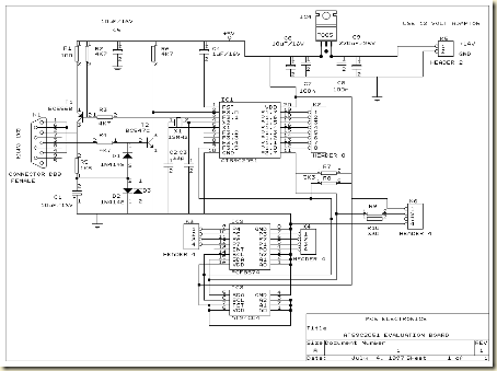
RS-232 interface, DB-9
Header for LCD display
I2C, PCF8574 I / O extender
AT24C04, I2C EEPROM
Next full text...
The circuit is more deserves to be called Evaluation Board AT89C2051 and AT89C4051. Some of the advantages of circuit Minimum System AT89C2051 / AT89C2051 and AT89C4051 Evaluation Board which I was present this time, hardware-hardware support below:
RS-232 interface, DB-9
Header for LCD display
I2C, PCF8574 I / O extender
AT24C04, I2C EEPROM
Class C Power Amplifier

If the amplifier class B need two transistors to work properly, then there are the so-called class C amplifier that only need 1 transistor. There are few applications that really only requires a positive phase only. An example is the pilot frequency detector and amplifier, RF tuner amplifier circuit and so forth.
Class C transistor amplifier active work only on the positive phase only, even if the need is quite narrow only the peaks are strengthened. Time signal can replica by series resonance of L and C. Typical of the series class C amplifier is like in the following series.
 |
| Basic Schematic Power Amplifier Class C |
The circuit is also not necessary created bias, because the transistor was deliberately made to work the saturation region. Series L C in the circuit will resonate and contributed important in re-replicate input signal into an output signal with the same frequency. This series if given the bait behind can be a series of RF oscillator is often used the transmitter. Class C amplifier have high efficiency even up to 100%, but fidelitas level is more low. But the actual High fidelitas not be purpose of this type of amplifier.
300W Power Amplifier Elektor
Taken by themselves, the properties of the PA300 amplifier are not revolutionary. But taken in combination, they show something special: a robust 300 watt hi-fi power amplifier that is not too difficult to build. There are several starting points to the design of a power amplifier: pure hi-fi without any compromise; simplicity and reliability; high output power. The design of the present amplifier is a mixture of these. The result is a unit that does not use esoteric components, is not too complex, and is fairly easily reproduced. In fact, it could well be named a Hi-fi public address amplifier.
There will be a few eyebrows raised at the power output of 300 watts (into 4Ohm); it is true, of course, that in the average living room 30–40 W per channel is more than sufficient. However, peaks in the reproduced music may have a power of 10–20 times the average level. This means that some reserve power is desirable. Also, there are loudspeakers around with such a low efficiency that a lot more than 30–40W is needed. And, last but not least, there are many people who want an amplifier for rooms much larger than the average living room, such as an amateur music hall.

the exception of an IC at the input, the circuit of the PA300 amplifier is conventional.
The New Technology of Auto Sound Systems
So what kind of auto sound system really seems to float your boat? Are you the type of person who wants the simplest sound system on the market today? Will you be content with talk radio and a few FM radio stations? Do you need an 8-track? How about a cassette player? I hate to say it, but if you are still living in the past, you will have a rather difficult time finding an audio system for your car that can accommodate your desire to hold technology behind the current trends. These things simply do not sell. You may find an occasional auto sound system that still has a cassette player but for the most part you will find that the market for this device is almost as limited as the quality of the device itself.
 Todays auto sound systems are more sophisticated than they have ever been before. Gone are the days when you had to turn a dial to find a radio station. Today you can set your car to scan the stations until you find one you like. You can even set them to scan radio stations by type. For me, that was a great invention as I find country music rather sad and always end up finding the one song that will bring uninvited torrents of tears while flipping through the stations mindlessly as I drive. Being someone that hates to cry on any given day it is bad enough to cry. Add to that the fact that Im probably driving at about 75 or so miles an hour and you can probably see where this is problematic. I do best whenever I can avoid country music stations all together.
Another great technological advance when it comes to the auto sound system is individual volume control. No longer do you have to listen to your mothers, brothers, sisters, or Aunt Sallys music blaring, you can slide on your headphones and mute out the noise of the rest of the world. If your vehicle has a truly sophisticated sound system, you can even change the radio station in order to find music that is much more suitable for your musical tastes.
You should also be aware that todays auto sound systems are much more user friendly than those of days past. Most displays are digital and easy to read. You might even notice that many can read the local radio stations codes and formats and will list the songs that are playing for you. Youll never have to wonder about the name of that great song you just heard or even who sang it again. Its right before your eyes as you are driving along and listening to awesome tunes.
The best auto sound systems offer not only CD options to drivers and passengers alike but also the ability and capability of reading and interpreting MP3 data as well. More and more people are turning to MP3s for their primary source of music. It takes up far less space than your average CD holder and holds a lot more music. You can download only the songs you like without purchasing an entire CD full of songs only to find that you only liked one song on the entire CD. You can put your favorite songs on a memory stick and bring them along for the ride. Its a great way to enjoy music in this day and age. Im quite literally surprised that I havent seen an iPod auto sound system pop up on the radar yet and am seriously expecting to see one any day now, literally.
Regardless of whether or not you wish to enter the modern era of music and music listening its upon us. However, if you are truly opposed we could always find you a nice supply of Sinatra in MP3 format in order to make the transition a little more comfortable for you.
Transmitter and Receiver Infra Red Headphone

Transmitter and receiver circuit using infra red audio signal is applied to emit an audio signal and will received on a headphones. Making his series is not too difficult, the transmitter and receiver circuit scheme can be seen below.
 |
| Transmiter schematics |
 |
| Receiver schematics |
After the series finished, you can try to give the audio inputs on the transmitter and point the LED transmitter to the receiver. Maximum distance is a few meters may not be more than 10 meters, but you can listen to music without wires while using infra red.
image[link]
Monday, September 23, 2013
Video Amplifier using BC560
 |
| Video Amplifier using BC560 Schematic Diagram |
The video amplifier in the diagram is a well-known design. Simple, yet very useful, were it not for the ease with which the transistors can be damaged if the potentiometers (black level and signal amplitude) are in their extreme position. Fortunately, this can be obviated by the addition of two resistors. If in the diagram R3 and R4 were direct connections, as in the original design, and P1 were fully clockwise and P2 fully anticlockwise, such a large base current would flow through T1 that this transistor would give up the ghost.
Moreover, with the wiper of P2 at earth level, the base current of T2 would be dangerously high. Resistors R3 and R4 are sufficient protection against such mishaps, since they limit the base currents to a level of not more than 5 mA. Shunt capacitor C4 prevents R4 having an adverse effect on the amplification.
Author: L.A.M. Prins
Copyright: Elektor Electronics
Source: http://www.extremecircuits.net/2010/07/video-amplifier.html
Audio Peak Indicator Circuit
The existence of the peak indicator "Audio Peak Indicator" in an audio device is needed. Audio Peak indicator is a simple circuit to detect the peak level of audio signal. Audio Peak indicator circuit is built with duabuah transistor and LED indicator as peak level detection of audio signals.
The main function of a series of Audio Peak indicator is to determine the occurrence of the peak level of audio signal that is more than +4 dB, equivalent to 1.25 V rms. If the received audio signal Audio Peak Indicator more than +4 dB was the LEDs in series Peak Audio This indicator will light. Audio Peak indicator circuit is mounted on the output audio system.
The main function of a series of Audio Peak indicator is to determine the occurrence of the peak level of audio signal that is more than +4 dB, equivalent to 1.25 V rms. If the received audio signal Audio Peak Indicator more than +4 dB was the LEDs in series Peak Audio This indicator will light. Audio Peak indicator circuit is mounted on the output audio system.

R1 = 10Kohm
R2 = 1.2Kohm
R3 = 220Kohm
R4-5 = 4.7Kohm
C1 = 47uF 25V
C2 = 2.2uF 25V
Q1-2 = BC550C
D1 = LED RED
We hope to form the reference materials in the manufacture of circuit pernagkat Audio Peak Indicators in the audio readers.
Subscribe to:
Posts (Atom)