Saturday, October 18, 2014
Build Emergency Light Alarm
Powered by two AA NI-CD batteries
Four switchable options

Four switchable options
Circuit diagram
Parts:
- R1 220K 1/4W Resistor
- R2 470R 1/2W Resistor
- R3 390R 1/4W Resistor
- R4 1K5 1/4W Resistor
- R5 1R 1/4W Resistor
- R6 10K 1/4W Resistor
- R7 330K 1/4W Resistor
- R8 470R 1/4W Resistor
- R9 100R 1/4W Resistor
- C1 330nF 400V Polyester Capacitor
- C2 10µF 63V Electrolytic Capacitor
- C3 100nF 63V Polyester Capacitor
- C4 10nF 63V Polyester Capacitor
- D1-D5 1N4007 1000V 1A Diodes
- D6 LED Green (any shape)
- D7 1N4148 75V 150mA Diode
- Q1,Q3,Q4 BC547 45V 100mA NPN Transistors
- Q2,Q5 BC327 45V 800mA PNP Transistors
- SW1,SW2 SPST Switches
- SW3 SPDT Switch
- LP1 2.2V or 2.5V 250-300mA Torch Lamp
- SPKR 8 Ohm Loudspeaker
- B1 2.5V Battery (two AA NI-CD rechargeable cells wired in series)
- PL1 Male Mains plug
Device purpose:
This circuit is permanently plugged into a mains socket and NI-CD batteries are trickle-charged. When a power outage occurs, the lamp automatically illuminates. Instead of illuminating a lamp, an alarm sounder can be chosen. When power supply is restored, the lamp or the alarm is switched-off. A switch provides a "latch-up" function, in order to extend lamp or alarm operation even when power is restored.
Circuit operation:
Mains voltage is reduced to about 12V DC at C2s terminals, by means of the reactance of C1 and the diode bridge (D1-D4). Thus avoids the use of a mains transformer. Trickle-charging current for the battery B1 is provided by the series resistor R3, D5 and the green LED D6 that also monitors the presence of mains supply and correct battery charging. Q2 & Q3 form a self-latching pair that start operating when a power outage occurs. In this case, Q1 biasing becomes positive, so this transistor turns on the self latching pair. If SW3 is set as shown in the circuit diagram, the lamp illuminates via SW2, which is normally closed; if set the other way, a square wave audio frequency generator formed by Q4, Q5 and related components is activated, driving the loudspeaker. If SW1 is left open, when mains supply is restored the lamp or the alarm continue to operate. They can be disabled by opening the main on-off switch SW2. If SW1 is closed, restoration of the mains supply terminates lamp or alarm operation, by applying a positive bias to the Base of Q2.
Cross Linking With Two Patch Cables
In networks, the supremacy of coax cable is a thing of the past. Nowadays, Ethernet connections are made using UTP cables. The BNC plug has yielded to the 8-way RJ45 plug. Previously, coax cables were daisy-chained from computer to computer and terminated at the two ends using 50-_ resistors, but modern networks use central ‘socket boxes’ (switches and/or hubs) to interconnect everything. The connections between the hubs and the computers are made using patch cables having the same sequence of leads in the RJ45 connectors at each end. For making a direct connection between two computers without using a hub or switch, a ‘crossover cable’ is used.


 Such a cable has the leads cross-linked in order to allow the two computers to directly communicate with each other. If there are problems with the network, it can be handy to be able to directly interconnect twocomputers, or directly connect a computer to a cable or ADSL modem without using a hub or switch. A long crossover cable is not always available, and shoving around computers is not an attractive alternative. Consequently, we can use a dual RJ45 wall outlet box to construct an adapter, which can be used to interconnect the two patch cables coming from the equipment in question. This outlet box must be wired to create a cross-linked connection. This is done by making the following internal connections:
Such a cable has the leads cross-linked in order to allow the two computers to directly communicate with each other. If there are problems with the network, it can be handy to be able to directly interconnect twocomputers, or directly connect a computer to a cable or ADSL modem without using a hub or switch. A long crossover cable is not always available, and shoving around computers is not an attractive alternative. Consequently, we can use a dual RJ45 wall outlet box to construct an adapter, which can be used to interconnect the two patch cables coming from the equipment in question. This outlet box must be wired to create a cross-linked connection. This is done by making the following internal connections:- 1 → 3
- 2 → 6
- 3 → 1
- 4 → 4
- 5 → 5
- 6 → 2
- 7 → 7
- 8 → 8
Simple Temperature Sensor Arduino
Hello people, it’s been a while since I have posted projects on this website. This semester was really busy, I didn’t have time to much else, but soon I will have my winter holiday (Here in south our summer holiday is from December to February).
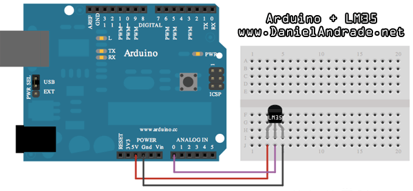
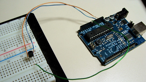
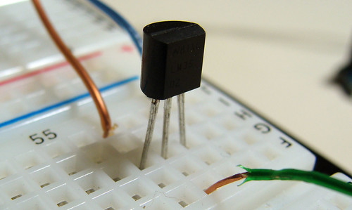
Today I am going to show you how to build a simple temperature sensor using one LM35 Precision Temperature Sensor and Arduino, so you can hookup on your future projects. The circuit will send serial information about the temperature so you can use on your computer, change the code as you will. I’m planning to build a temperature sensor with max/min + clock + LCD, and when I get it done, I will post here.
Parts:
This is a quick and simple step. Just connect the 5V output from arduino to the 1st pin of the sensor, ground the 3rd pin and the 2nd one, you connect to the 0 Analog Input.
Down goes some pictures that may help you, click to enlarge:


Here is the Arduino Code, just upload it and check the Serial Communication Option.
You can also download the .pde HERE.
Anything just ask!
Source by : link
Today I am going to show you how to build a simple temperature sensor using one LM35 Precision Temperature Sensor and Arduino, so you can hookup on your future projects. The circuit will send serial information about the temperature so you can use on your computer, change the code as you will. I’m planning to build a temperature sensor with max/min + clock + LCD, and when I get it done, I will post here.
Parts:
- Arduino (You can use other microcontroller, but then you will need to change the code).
- LM35 Precision Centigrade Temperature Sensor, you can get from any electronic store. Here is the DATA SHEET.
- BreadBoard
This is a quick and simple step. Just connect the 5V output from arduino to the 1st pin of the sensor, ground the 3rd pin and the 2nd one, you connect to the 0 Analog Input.
Down goes some pictures that may help you, click to enlarge:
Here is the Arduino Code, just upload it and check the Serial Communication Option.
You can also download the .pde HERE.
/*
An open-source LM35DZ Temperature Sensor for Arduino. This project will be enhanced on a regular basis
(cc) by Daniel Spillere Andrade , http://www.danielandrade.net
http://creativecommons.org/license/cc-gpl
*/
int pin = 0; // analog pin
int tempc = 0,tempf=0; // temperature variables
int samples[8]; // variables to make a better precision
int maxi = -100,mini = 100; // to start max/min temperature
int i;
void setup()
{
Serial.begin(9600); // start serial communication
}
void loop()
{
for(i = 0;i< =7;i++){ // gets 8 samples of temperature
samples[i] = ( 5.0 * analogRead(pin) * 100.0) / 1024.0;
tempc = tempc + samples[i];
delay(1000);
}
tempc = tempc/8.0; // better precision
tempf = (tempc * 9)/ 5 + 32; // converts to fahrenheit
if(tempc > maxi) {maxi = tempc;} // set max temperature
if(tempc < mini) {mini = tempc;} // set min temperature
Serial.print(tempc,DEC);
Serial.print(" Celsius, ");
Serial.print(tempf,DEC);
Serial.print(" fahrenheit -> ");
Serial.print(maxi,DEC);
Serial.print(" Max, ");
Serial.print(mini,DEC);
Serial.println(" Min");
tempc = 0;
delay(1000); // delay before loop
}
Anything just ask!
Source by : link
LIGHT ALARMS

LIGHT ALARM - 1
This circuit operates when lightweight|the sunshine} Dependent Resistor receives light. When no lightweight falls on the LDR, its resistance is high and also the transistor driving the speaker isnt turned on. When lightweight falls on the LDR its resistance decreases and also the collector of the second transistor falls. This turns off the primary transistor slightly via the second 100n and also the initial 100n puts a further spike into the bottom of the second transistor. This continues till the second transistor is turned on as onerous because it will go. the primary 100n is currently nearly charged and it cannot keep the second transistor turned on. The second transistor starts to turn off and each transistors swap conditions to provide the second half of the cycle.
This circuit operates when lightweight|the sunshine} Dependent Resistor receives light. When no lightweight falls on the LDR, its resistance is high and also the transistor driving the speaker isnt turned on. When lightweight falls on the LDR its resistance decreases and also the collector of the second transistor falls. This turns off the primary transistor slightly via the second 100n and also the initial 100n puts a further spike into the bottom of the second transistor. This continues till the second transistor is turned on as onerous because it will go. the primary 100n is currently nearly charged and it cannot keep the second transistor turned on. The second transistor starts to turn off and each transistors swap conditions to provide the second half of the cycle.
LIGHT ALARM - 2

This circuit is comparable to lightweight Alarm -1 however produces a louder output as a result of the speaker being connected directly to the circuit. The circuit is essentially a high-gain amplifier thats turned on initially by the LDR and then the 10n keeps the circuit turning on till it will activate no more. The circuit then starts to show off and eventually turns off utterly. the present through the LDR starts the cycle once more.
LIGHT ALARM - 3 (MOVEMENT DETECTOR)
This circuit is extremely sensitive and may be placed in a very space to detect the movement of a person up to a pair of metres from the unit.

The circuit is essentially a high-gain amplifier (made of the primary 3 transistors) that is turned on by the LDR or photo Darlington transistor. The third transistor charges the 100u via a diode and this delivers turn-on voltage for the oscillator. The LDR has equal sensitivity to the photo transistor during this circuit.
Eliminator 1 5 Volt battery using LM317
This circuit is a battery eliminator 1.5 V, that is, a power supply of 1.5 volts, low consumption that takes as input the output of the USB PC or notebook. The power adapter is simple, it converts the voltage from 5V to 1.5V USB ports, using the popular LM317 IC and a few other components. To be exact this circuit uses only three components, one is the LM317, R1 = R2 = 470 ohm and 100 ohm.
Eliminator 1.5 Volt battery using LM317 Circuit Diagram

Subscribe to:
Posts (Atom)